Evaporative humidifier
A humidifier and evaporative technology, applied in the air humidification system, heating method, lighting and heating equipment, etc., can solve the problems of high cost, power consumption, complex structure, etc., and achieve the effect of simple structure and low cost
- Summary
- Abstract
- Description
- Claims
- Application Information
AI Technical Summary
Problems solved by technology
Method used
Image

Examples
Embodiment 1
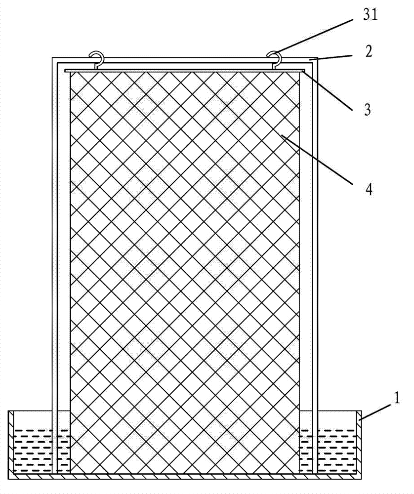
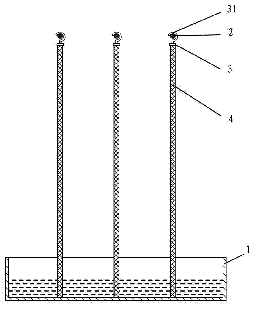
[0047] like figure 1 The shown evaporative humidifier includes a support frame 2, a hanger 3 and a flexible evaporation surface body 4, the hanger 3 is disassembled from the support frame 2, and the hanger 3 is specifically installed on the The support frame 2; the flexible evaporating surface body 4 is hooked on the hanger 3, and the water absorption of the flexible evaporating surface body 4 can be greater than its own weight.
[0048] In this embodiment, in order to enhance the stability of the evaporative humidifier, the supporting frame is connected to the base, and the base in this embodiment is set as the water container 1 .
[0049] Optionally, the hanger 3 can also be omitted, and the flexible evaporation surface body 4 will be directly supported on the supporting frame 2 .
[0050] Optionally, the base can also be a base with the function of holding water; a water container 1 can also be placed under the flexible evaporation surface body 4 .
[0051] like figure...
Embodiment 2
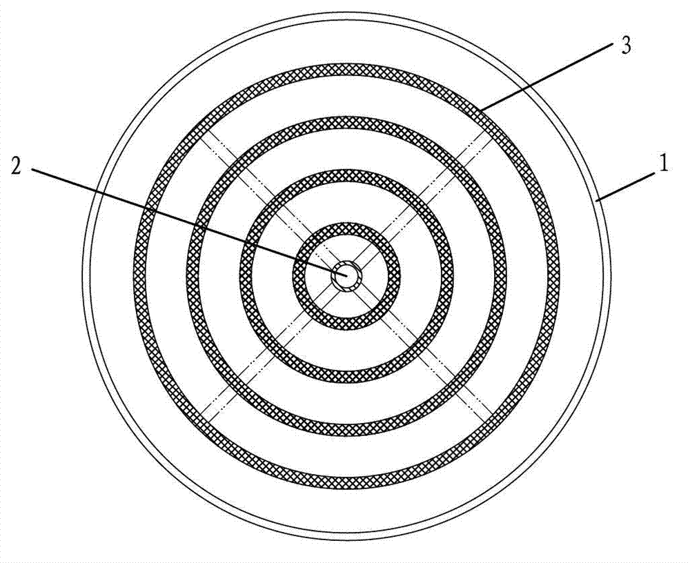
[0055] like image 3Shown is the top view of the evaporative humidifier of this embodiment, and its difference from Embodiment 1 is that the water container 1 is omitted in this embodiment, and the hanging part 3 is set as a collar, specifically including four inner and outer four Layer ring structure, each ring structure is hung with the flexible evaporation surface body 4. The hanger 3 is detachably mounted on the support frame 2 through a cross-shaped support structure.
[0056] Such as Figure 4 Shown is a front sectional view of the evaporative humidifier of this embodiment, and it can be seen that the flexible evaporating surface body 4 forms a plurality of annular columnar spaces. The air above and below the flexible evaporation surface body 4 forms convection, which is more conducive to the diffusion of water vapor and has a better humidification effect.
[0057] Optionally, the hanger 3 can also be set in other shapes, for example Figure 5 The clockwork shown, I...
Embodiment 3
[0059] Such as Figure 16 The evaporative humidifier shown is based on Example 1: the evaporative humidifier also includes a high-level water storage tank 5, the high-level water storage tank 5 is arranged on the hanger 3, and the high-level water storage tank 5 is connected to the flexible evaporating surface body 4 in a waterway, specifically, a drip hole 51 is provided at the bottom of the high-level water storage tank 5 , and the drip hole 51 is located above the flexible evaporating surface body 4 .
[0060] This embodiment cancels the water container 1 in the embodiment 1. In specific use, a certain amount of water can be stored in the high-level water storage tank 5 through the water injection hole 52 in advance, and the water can be slowly dripped into the flexible evaporation surface body 4 to supplement the water in the flexible evaporation surface body 4. moisture.
PUM
 Abstract
Description
Claims
Application Information
 - R&D
- Intellectual Property
- Life Sciences
- Materials
- Tech Scout
- Unparalleled Data Quality
- Higher Quality Content
- 60% Fewer Hallucinations
Browse by: Latest US Patents, China's latest patents, Technical Efficacy Thesaurus, Application Domain, Technology Topic, Popular Technical Reports.
© 2025 PatSnap. All rights reserved.Legal|Privacy policy|Modern Slavery Act Transparency Statement|Sitemap|About US| Contact US: help@patsnap.com