Non-contact modal test system and method

A modal test, non-contact technology, applied in vibration test, machine/structural component test, measuring device, etc., can solve the problem of changing the inherent vibration characteristics of the system, changing the structural mass distribution of the plate to be tested, and the test results are very different And other issues

Inactive Publication Date: 2013-04-17
BEIHANG UNIV
View PDF6 Cites 35 Cited by
  • Summary
  • Abstract
  • Description
  • Claims
  • Application Information

AI Technical Summary

Problems solved by technology

However, for light and small structures, especially common light plate structures, the test results often have large errors
The reason is that the additional mass brought by the sensor and the vibrator is very close to the structural mass of the board to be tested, or even greater than the structural mass of the board to be tested, thus greatly changing the mass distribution of the board to be tested
In addition, if the exciter is used as the excitation source, it will also bring a certain additional stiffness to the system
These factors will completely change the natural vibration characteristics of the system, causing the test results to be far from the actual

Method used


Image

  • Non-contact modal test system and method

Examples


Embodiment Construction

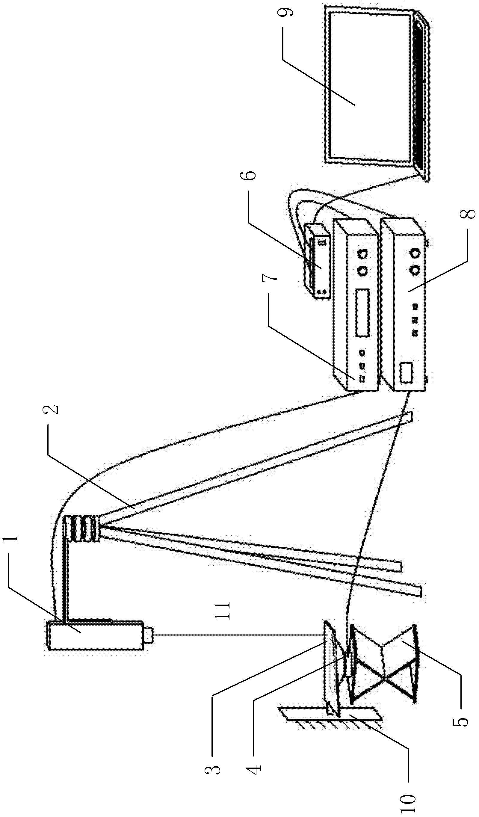
[0029] figure 1 The configuration of the non-contact modal testing system according to an embodiment of the present invention is shown, wherein the structure 3 to be tested needs to be firmly installed on the bearing wall 10 in advance. The excitation speaker 4 is held up by the speaker support 5 and placed under the board structure to be tested. The upper surface of the loudspeaker 4 is parallel to the structure 3 to be tested with a gap of 1-5 mm.

[0030] The laser head 1 is supported by the tripod 2 , placed above the structure to be measured 3 , aimed at the point to be measured, and used to emit laser light 11 .

[0031] In a specific embodiment of the present invention, the laser head 1 is a Polytech OFV-505 laser head.

[0032] The excitation speaker 4 is connected with the output end of the speaker power amplifier 8 with a cable; the laser head 1 is connected with the input end of the vibration measurement controller 7 with a cable; the input end of the speaker powe...


PUM


Abstract

The invention relates to a non-contact modal test system and method. The method comprises the following steps: driving a shock excitation loudspeaker (4) to emit a sound wave and arousing a to-be-tested structure (3) to vibrate, wherein the shock excitation loudspeaker (4) is arranged under the to-be-tested structure (3), an upper surface of the shock excitation loudspeaker (4) is generally parallel to the to-be-tested structure (3) and a clearance is formed; and emitting laser through a laser head (1) and detecting a laser signal reflected by a to-be-tested point on the to-be-tested structure (3), wherein the laser head (1) is arranged above the to-be-tested structure (3). The non-contact modal test system and method provided by the invention have the advantages that a shock excitation source is not in contact with the to-be-tested plate structure, so that no additional mass and additional rigidity are brought to the system; a sensor (laser head) is not in contact with the to-be-tested plate structure, so that no additional mass is brought to the system; when the excitation is a sinusoidal signal, a sand molding method (placing quartz sand on the structure) is adopted for determinatively obtaining the modal frequency and vibration mode of the structure (macroscopic); and when the excitation is a white noise signal, the modal frequency and vibration mode of the structure can be analyzed and obtained by only collecting vibration signals.

Description

technical field [0001] The invention relates to a non-contact modal testing method, which is used for modal testing of light plate structures in the field of vibration testing. Background technique [0002] Modal analysis is an important method for structural dynamic design and equipment fault diagnosis. As the basis of modal analysis, modal testing is an effective way to study the vibration characteristics of various structures, and it plays an important role in the design of buildings, ships, automobiles, and aircraft. [0003] In the traditional modal test, people usually paste the sensor on the structure to be tested, and use a hammer or a vibrator to apply excitation to obtain the frequency response characteristics of the structure. This method has good measurement accuracy in the modal test of large structures (mainly reflected in large mass and high stiffness), and can obtain credible test results. However, for light and small structures, especially common light pla...

Claims


Application Information

Patent Timeline
Patent Type & Authority Applications(China)
IPC IPC(8): G01M7/02G01H9/00
Inventor 吴志刚张仁嘉周礼洋马成骥
Owner BEIHANG UNIV
Why Eureka
Try Eureka