Eureka AIR delivers breakthrough ideas for toughest innovation challenges, trusted by R&D personnel around the world.

Method for measuring electrode current through electrode current measuring device for low voltage compensation of submerged arc furnace

A technology for electrode current and measuring devices, which is applied in the direction of measuring devices, measuring current/voltage, and measuring electrical variables, etc. It can solve problems such as inability to obtain electrode currents correctly, electrode currents cannot truthfully reflect electrode current conditions, and affect the rationality of electrode operation , to achieve the effect of simple and convenient installation, small installation space and wide measurement range

Inactive Publication Date: 2015-07-15
北京思能达电力电子技术有限公司
View PDF5 Cites 0 Cited by
  • Summary
  • Abstract
  • Description
  • Claims
  • Application Information

AI Technical Summary

Problems solved by technology

[0006] At present, almost all electrode current parameters adopt the method of converting the high-voltage side current. Although this method is simple and convenient, due to the influence of the iron loss and copper loss of the transformer, and the impedance and inductance of the low-voltage short network, the converted electrode current It cannot faithfully reflect the real electrode current situation. Due to the participation of the compensation current when there is low-voltage reactive power compensation, this method cannot obtain the electrode current correctly. Therefore, this type of current sampling method seriously affects the rationality of the electrode operation.

Method used


Image

  • Method for measuring electrode current through electrode current measuring device for low voltage compensation of submerged arc furnace
  • Method for measuring electrode current through electrode current measuring device for low voltage compensation of submerged arc furnace
  • Method for measuring electrode current through electrode current measuring device for low voltage compensation of submerged arc furnace

Examples


Embodiment Construction

[0026] In order to enable the examiner to further understand the structure, features and other purposes of the present invention, the attached preferred embodiments are now described in detail with the attached drawings as follows, and the illustrated embodiments using the drawings are only used to illustrate the technology of the present invention scheme, not to limit the present invention.

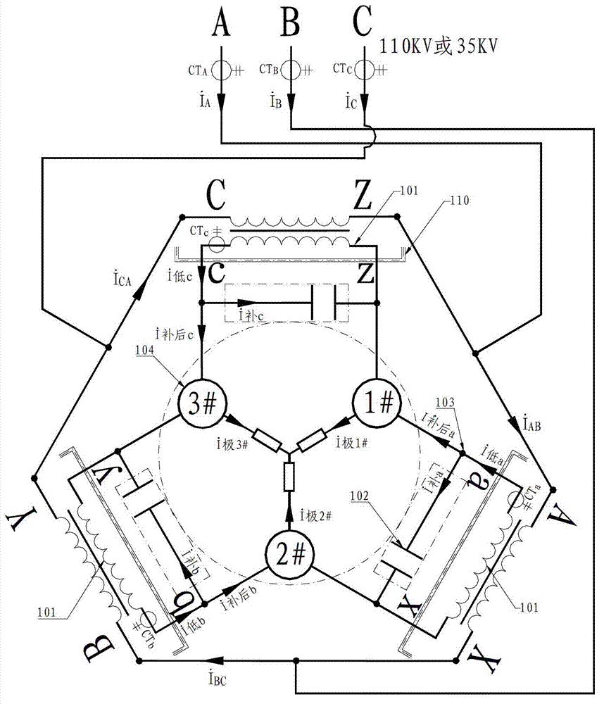
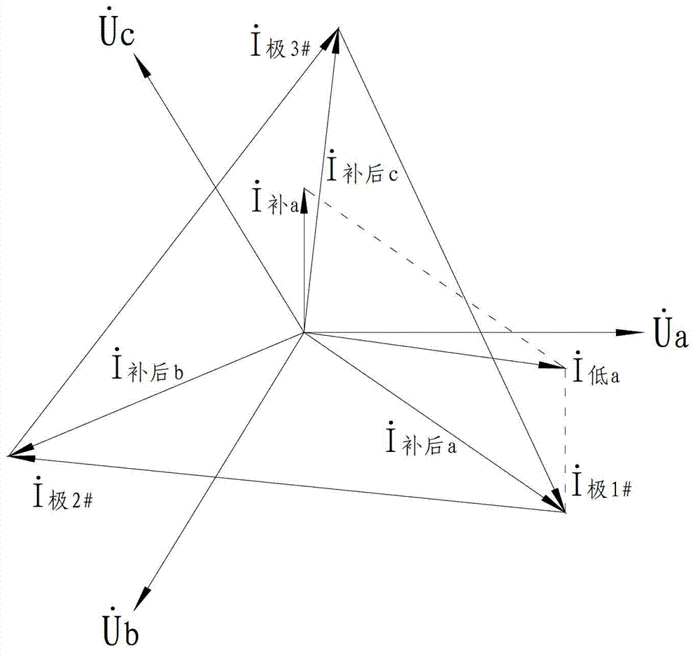
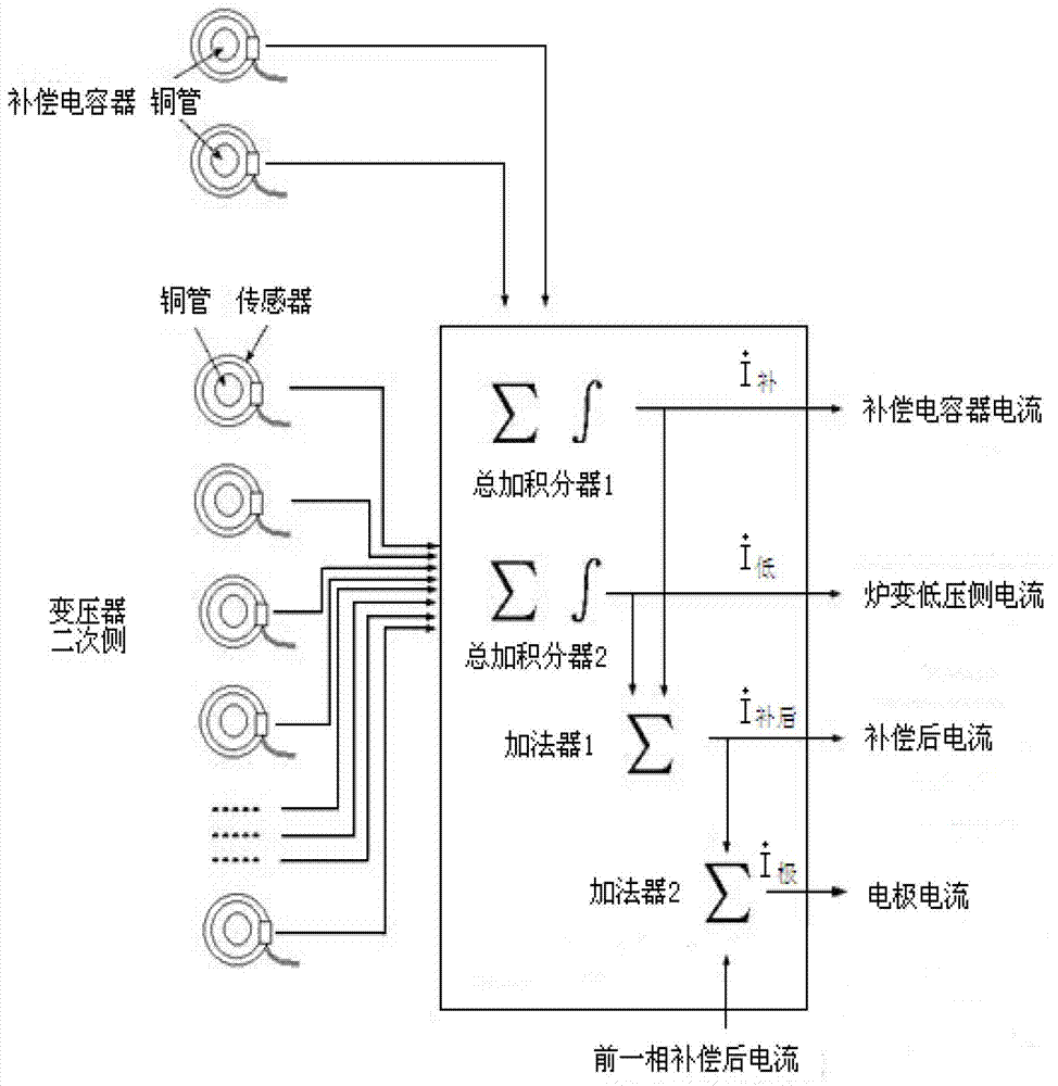
[0027] Such as figure 1 as shown, figure 1 It is a schematic diagram of the current transmission system of the submerged arc furnace. in, figure 1 The inside of the dotted line circle is the internal system of the furnace body, the dotted line box is the reactive power compensation system, and the rest are transformers and short network systems. Depend on figure 2 The vector synthesis method applied to the electrode current measuring device can be obtained from the current reference direction shown in .

[0028] Such as figure 1 As shown, in the low-voltage reactive power compensa...


PUM


Abstract

The invention provides a method for measuring electrode current through an electrode current measuring device for low voltage compensation of a submerged arc furnace. The method for measuring the electrode current comprises the following steps that a Rogowski coil output signal is a differential voltage signal of primary current; a first summing integrator performs vector summing integration on the signal to obtain capacitance compensation current; a second summing integrator performs vector summing integration on the signal to obtain furnace transformation low-voltage-side current; the capacitance compensation current and the furnace transformation low-voltage-side current are sent to a first adder and subjected to vector subtraction calculation to obtain compensated current on a short net behind a low voltage compensation access point; the compensated current is sent to a second adder; and front-phase compensated current is sent to the current-phase second adder, and is subtracted from the current-phase compensated current to obtain current-phase electrode current. The method has the characteristics of accurate measurement, wide measurement range, convenience for installation and simple structure.

Description

technical field [0001] The invention relates to large current measurement in the field of metallurgical industry, in particular to a method for measuring electrode current through an electrode current measuring device used for low pressure compensation of a submerged arc furnace. Background technique [0002] The submerged arc furnace is an industrial electric furnace that consumes a lot of power. The current of the low-voltage side of the furnace transformer (also known as the submerged arc furnace transformer) is mostly tens of thousands or even hundreds of thousands of amperes. The side current transformer samples, and then converts the electrode current, such as figure 1 Shown, CT A , CT B , CT C It is a current transformer set on the high-voltage side, which detects the line current on the high-voltage side Then convert the electrode current according to the gear ratio of the furnace transformer Due to the influence of the iron loss and copper loss of the transfo...

Claims


Application Information

Patent Timeline
Patent Type & Authority Patents(China)
IPC IPC(8): G01R19/00
Inventor 郑元彬李俊彪
Owner 北京思能达电力电子技术有限公司
Why Eureka
Eureka Blog
Learn More