Stator-free dual-electric brush dual-rotor outer circle permanent magnet synchronous motor

A technology of synchronous motors and permanent magnets, applied in the direction of electric components, electrical components, electromechanical devices, etc., can solve the problems of complex control mechanisms, increased probability of wear and tear, and large volume, and achieve reduced manufacturing complexity, reduced volume, and Mitigation effects on operational stability and service life

Inactive Publication Date: 2013-04-17
张建龙 +1
View PDF4 Cites 7 Cited by
  • Summary
  • Abstract
  • Description
  • Claims
  • Application Information

AI Technical Summary

Problems solved by technology

But because it can be regarded as two independent ordinary motors, there must be two controllers, which makes the control mechanism more complicated, and for the motor body, because there is still a stator part in the structure, the volume is relatively large
At the same time, the inverter is fixed outside the motor, and the connection between the output end of the inverter and the input end of the motor basically adopts the connection method of three brushes. The increase in the number of brushes will lead to an increase in the probability of wear and failure.

Method used


Image

  • Stator-free dual-electric brush dual-rotor outer circle permanent magnet synchronous motor

Examples


Embodiment Construction

[0025] The present invention will be described in detail below in conjunction with specific embodiments. The following examples will help those skilled in the art to further understand the present invention, but do not limit the present invention in any form. It should be noted that those skilled in the art can make several modifications and improvements without departing from the concept of the present invention. These all belong to the protection scope of the present invention.

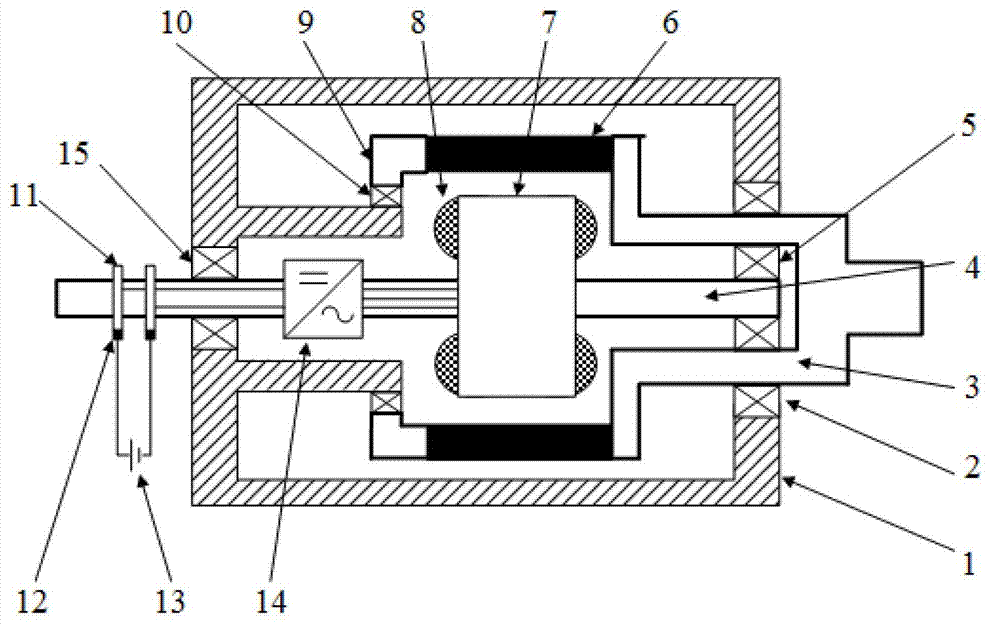
[0026] Such as figure 1 As shown, this embodiment includes a casing 1, an outer rotor and an inner rotor, the outer rotor includes an outer shaft 3, the inner end of the outer shaft 3 is arranged inside the casing 1, and the inner ends of the outer shaft 3 are staggered along the circumferential direction The permanent magnet 6 is provided with an end cap 9 at its end, and the outer end of the outer rotating shaft 3 protrudes outside the first end of the casing 1; the inner rotor includes an inner...


PUM


Abstract

The invention discloses a stator-free dual-electric brush dual-rotor outer circle permanent magnet synchronous motor, which comprises a housing, an outer rotor and an inner rotor. The outer rotor comprises an outer rotating shaft. The inner end of the outer rotating shaft is arranged in the housing. Permanent magnets are circumferentially arranged at the inner end of the outer rotating shaft in a staggered way. An end cover is arranged on the inner end part of the outer rotating shaft. The outer end of the outer rotating shaft extends from the first end of the housing. The inner rotor comprises an inner rotating shaft. The inner end of the inner rotating shaft is arranged in the outer rotor. An inner rotor core and an inner rotor winding embedded into the inner rotor core are arranged at the inner end of the inner rotating shaft. The outer end of the inner rotating shaft extends from the second end, which is opposite to the first end, of the housing. Two slip rings are arranged in a way of being close to the end part at the outer end of the inner rotating shaft. Electric brushes are connected to the slip rings respectively. An inverter is arranged on the inner rotating shaft between the second end of the housing and the inner rotor core in the housing. The motor is simple in structure and applicable to various places; the limitation that an ordinary motor is provided with only one rotating shaft does not exist; and a stator part is eliminated.

Description

technical field [0001] The invention relates to the technical field of motors, in particular to a statorless two-brush and double-rotor outer ring permanent magnet synchronous motor. Background technique [0002] The dual-rotor motor has two rotors and rotating shafts with independent rotational speeds, which can realize dual-axis independent drive, so it has broad application prospects in various occasions, such as the electric drive system of hybrid vehicles, the electric stepless motor of automobiles and wind turbines Transmission and modern machine tool CNC turntable, etc. [0003] At present, the double-rotor permanent magnet motor that has been published at home and abroad is a new type of motor that is set together with an outer rotor permanent magnet motor and an inner rotor permanent magnet motor and shares a stator. But because it can be regarded as two independent ordinary motors, there must be two controllers, which makes the control mechanism more complicated, ...

Claims


Application Information

Patent Timeline
Patent Type & Authority Applications(China)
IPC IPC(8): H02K16/02H02K1/26H02K1/27H02K5/16
Inventor 殷承良张希沈辉
Owner 张建龙
Why Eureka
Try Eureka