Bearing auto-feed device

A technology of automatic feeding and feeding, which is applied in the directions of conveyor objects, transportation and packaging, skids, etc., can solve the problems of unqualified products and low production efficiency, and achieve the effect of improving work efficiency and product qualification rate and reducing energy consumption.

Active Publication Date: 2013-04-24
ZHEJIANG HMC
View PDF4 Cites 10 Cited by
  • Summary
  • Abstract
  • Description
  • Claims
  • Application Information

AI Technical Summary

Problems solved by technology

[0005] The purpose of the present invention is to provide an automatic bearing feeding device, which uses the gravity of the bearing itself and a set of feeding mechanism and control system to realize the automatic feeding and positioning of the bearing, and overcomes the defects of low production efficiency and unqualified products in the prior art

Method used


Image

  • Bearing auto-feed device
  • Bearing auto-feed device
  • Bearing auto-feed device

Examples


Embodiment

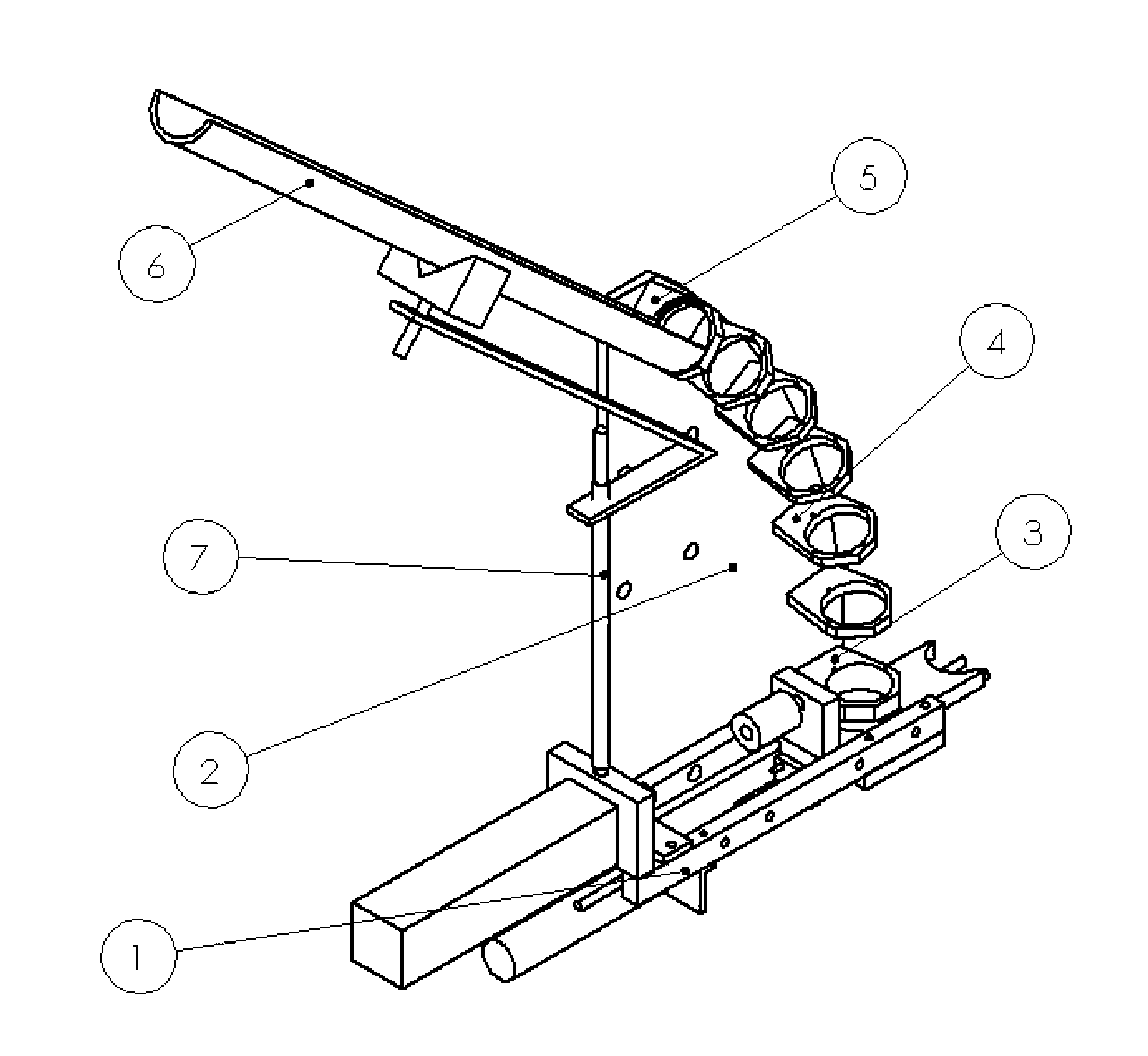
[0032] see figure 1 , including in the figure: feeding fixed plate 2, feeding half pipe 6, support rod 7, feeding upper bending ring 5, feeding middle bending ring 4, feeding lower bending ring 3 and feeding mechanism 1. The upper bending ring 5 for feeding, the middle bending ring 4 for feeding, the lower bending ring 3 for feeding and the feeding mechanism 1 are fastened on the feeding fixed plate 2 respectively. Feeding semi-pipe 6 one end is stuck on the upper bending ring 5 of feeding, and the other end is supported by support rod 7, and support rod 7 is fastened on the feeding mechanism 1.

[0033] The feeding half-pipe 6 in this embodiment is an elongated tile-mounted structure, and the inner surface of the tile-mounted structure is the running channel of the bearing. The feeding channel is composed of the feeding half pipe 6, the feeding upper bending ring 5, the feeding middle bending ring 4, and the feeding lower bending ring 3. Here, a straight feeding channel can ...


PUM


Abstract

The invention discloses a bearing auto-feed device which comprises a feeding fixed plate. A feeding upper bent ring, a feeding middle bent ring, a feeding lower bent ring and a feeding mechanism are fixed on the feeding fixed plate sequentially. Each of the feeding upper bent ring, the feeding middle bent ring and the feeding lower bent ring is provided with a round opening allowing a bearing to pass. The inner diameter of the round openings is slightly larger than the outer diameter of the bearing. A feeding half tube is arranged above the feeding upper bent ring. The back of the feeding half tube is supported by a support rod. The bottom end of the support rod is disposed on the feeding mechanism. The feeding mechanism comprises a feeding chute, a push plate, a push plate cylinder, a pull rod, a pull rod cylinder and two linear bearings. By the aid of weight of the bearing and the ingenious design of feeding mechanical structure, the bearing auto-feed device needs no filtering and sorting equipment for automatic feeding, such as electromagnetic vibrating feeders, so that energy consumption is lowered greatly. In addition, both operating efficiency and product yield of the bearing auto-feed device are increased greatly.

Description

technical field [0001] The invention belongs to the field of mechanical design and manufacture and its automation, in particular to an automatic feeding device for bearings. Background technique [0002] Bearing is an important mechanical component in modern mechanical equipment. It plays a key role in the movement, function, work and efficiency of machinery, and directly determines the quality and life of mechanical equipment. [0003] In the existing assembly of components or assemblies that require bearings, the way of loading the bearings is generally manual assembly. Specifically, the workers directly put the bearings in the designated position by hand, and then press the bearings in place. [0004] The positioning method for bearings in the prior art is directly operated by workers, which is easy to dirty the bearings, and the consistency of bearing placement is poor, so the work efficiency is low, the product failure rate is high, and at the same time, it is dependent...

Claims


Application Information

Patent Timeline
IPC IPC(8): B65G47/82B65G11/00
Inventor 马翔朱永中
Owner ZHEJIANG HMC
Why Eureka
Try Eureka