Combination line-shaped bearing cable suspension bridge and construction method thereof

A cable and linear technology, which is applied to a suspension bridge combined with linear load-bearing cables and its construction field, can solve the problems of small inclination angle of the suspension cable, small lateral stability of the carriageway beam, insufficient lateral stability, etc., and achieves enhanced stability and convenient construction. Effect

Active Publication Date: 2013-04-24
张志新
View PDF5 Cites 14 Cited by
  • Summary
  • Abstract
  • Description
  • Claims
  • Application Information

AI Technical Summary

Problems solved by technology

When this structure is used for long-span, the lateral stability is insufficient. Therefore, Yang Yongxin, Ge Yaojun, and Xiang Haifan mentioned in "Exploration for Improving the Wind-resistant Stability of Long-span Suspension Bridge" that the more economical and effective method is: center the main cable, form triangles with slings and stiffeners, such as figure 1 As shown, but due to the need to ensure traffic clearance, the main cable cannot be rigidly connected to the bridge deck in the mid-span (that is, the central buckle)
[

Method used


Image

  • Combination line-shaped bearing cable suspension bridge and construction method thereof
  • Combination line-shaped bearing cable suspension bridge and construction method thereof
  • Combination line-shaped bearing cable suspension bridge and construction method thereof

Examples


Embodiment 1

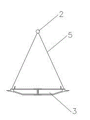
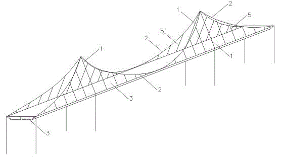
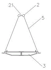
[0031] Such as image 3 , Figure 4 Shown, the suspension bridge of combined linear load-bearing cable of the present invention is made of bridge tower (1), load-bearing cable (2), carriageway beam (3), anchorage (4), sling (5), and load-bearing cable is made of two The two main cables are placed on two saddles on the top of the bridge tower (1). The distance between the saddles is less than the width of the carriageway girder and greater than 2 meters. The middle part of the mid-span is anchored on both sides of the carriageway girder (3) of the mid-span, and the two main cables are provided with a main cable displacement rod (24) between the bridge tower (1) and the mid-span anchor point of the mid-span, and the bridge tower The main cables to the displacement pull rods are parallel, and a strut (21) is arranged between the two main cables; wherein, the strut (21) has a hoop (241), which is controlled by the length of the pull rod (242). The distance between the main cable...

Embodiment 2

[0043] Such as Figure 8 As shown, the displacement pull rod of the present invention is composed of two baffles (243) and two pull rods (242), the two ends of the pull rods (242) are respectively connected to the two baffles (243), and the inside The side is in contact with the main cable, and its surface is consistent with the shape of the main cable at the corresponding position. The length of the tie rods is based on keeping the two main cables parallel between the bridge tower and the displacement tie rods, and is determined by calculation according to the overall stability and force requirements of the structure. Strength of tie rods (242) and baffles (243). Rigid rods are set between part of the cable clamps to form a strut together with the cable clamps.


PUM


Abstract

The invention relates to a combination line-shaped bearing cable suspension bridge which is formed by a carriageway beam, a bridge tower, an anchoring, a bearing cable, and suspender cables. The bearing cable is formed by two main cables. A main cable displacement pulling rod of the two main cables is arranged between the bridge tower and an anchoring point. The main cables between the bridge tower and the displacement pulling rod are parallel to each other. The main cables between the displacement pulling rod and the anchoring point are in curve shapes at different intervals. The suspender cables are connected at two sides of the main cables and stiff girders at different skew angles. A main cable plane locating process exists in a construction method of the combination line-shaped bearing cable suspension bridge. According to the combination line-shaped bearing cable suspension bridge and the construction method of the combination line-shaped bearing cable suspension bridge, a dip angle of the suspender cables of the suspension bridge can be enlarged, an approximate triangle structure is formed by the carriageway beam and a part of the suspender cables, and stability of the suspension bridge is strengthened.

Description

technical field [0001] The invention relates to a bridge structure and a construction method, in particular to a suspension bridge combined with linear load-bearing cables and a construction method thereof. Background technique [0002] A suspension bridge is a long-span bridge. Known suspension bridge structure is made of bridge pylon, anchorage, load-bearing cable, driveway beam and sling, load-bearing cable is vertical curve, two ends are fixed on the anchorage, is connected load-bearing cable and driveway beam by sling. When this structure is used for long-span, the lateral stability is insufficient. Therefore, Yang Yongxin, Ge Yaojun, and Xiang Haifan mentioned in "Exploration for Improving the Wind-resistant Stability of Long-span Suspension Bridge" that the more economical and effective method is: center the main cable, form triangles with slings and stiffeners, such as figure 1 As shown, but due to the need to ensure traffic clearance, the main cable cannot be rigi...

Claims


Application Information

Patent Timeline
IPC IPC(8): E01D11/02E01D19/16E01D21/00
Inventor 张志新
Owner 张志新
Why Eureka
Try Eureka