Magnetorheological fluid speed bump

A technology of magneto-rheological fluid and speed bumps, applied in roads, road signs, traffic signals, etc., can solve problems such as reduced vehicle speed, enhanced vehicle vibration, and vehicle damage, and achieves reduced rigid contact and force, flexible changes in stiffness, The effect of prolonging the service life

Inactive Publication Date: 2013-04-24
SHANGHAI UNIV OF ENG SCI
View PDF6 Cites 56 Cited by
  • Summary
  • Abstract
  • Description
  • Claims
  • Application Information

AI Technical Summary

Problems solved by technology

[0004] One is that the deceleration belt cannot flexibly adjust the deceleration effect on passing vehicles according to different vehicle speeds. It can certainly have a better deceleration effect when the vehicle speed is high, but when the vehicle speed is low enough, due to the existence of the deceleration belt, it will still make the car interior Passengers obviously feel the bumps, which reduces the comfort of driving. This kind of "equal treatment" deceleration effect cannot guide the driver to reduce the speed as much as possib

Method used


Image

  • Magnetorheological fluid speed bump
  • Magnetorheological fluid speed bump

Examples


Embodiment Construction

[0034] The present invention will be further described below in conjunction with accompanying drawing.

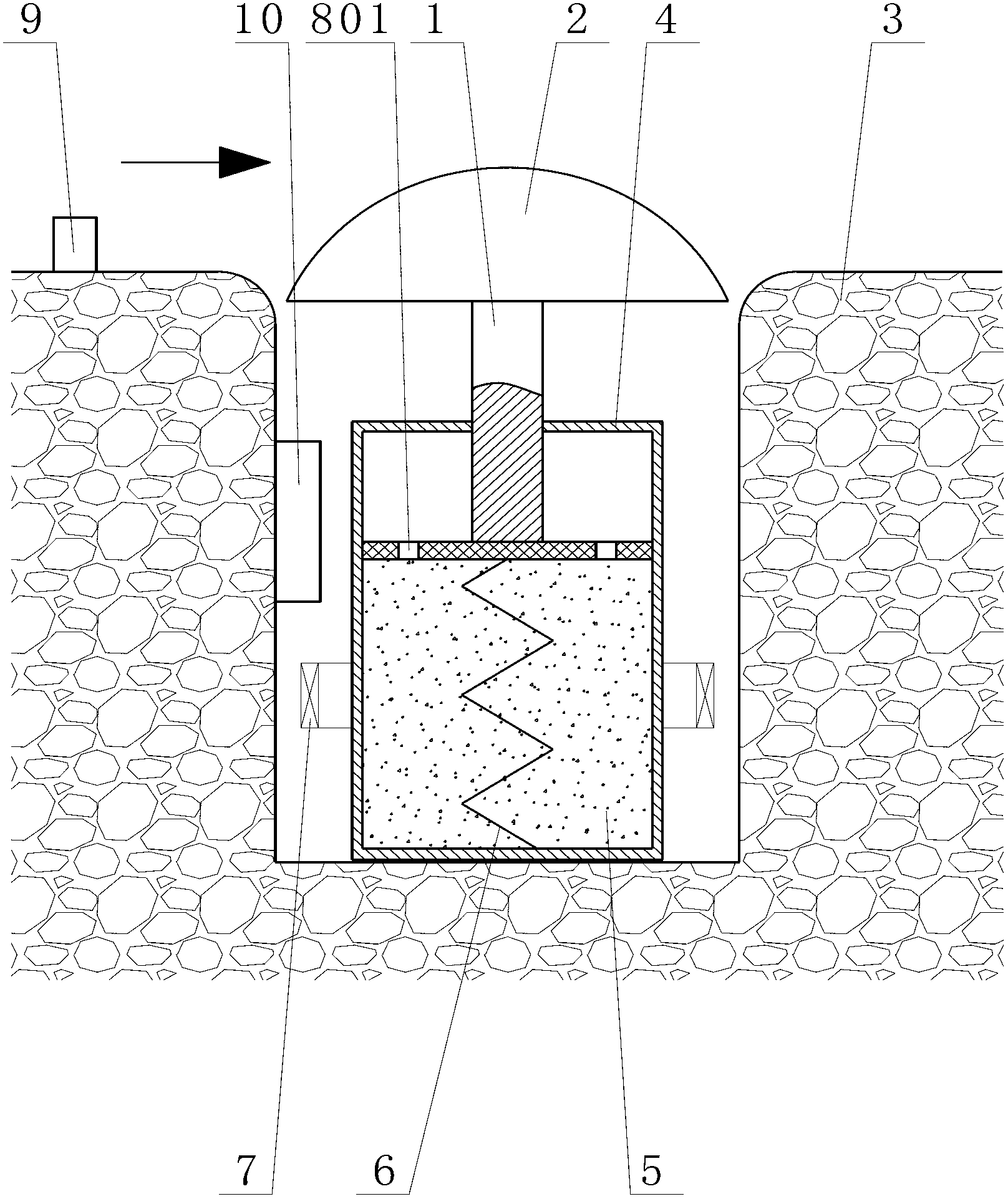
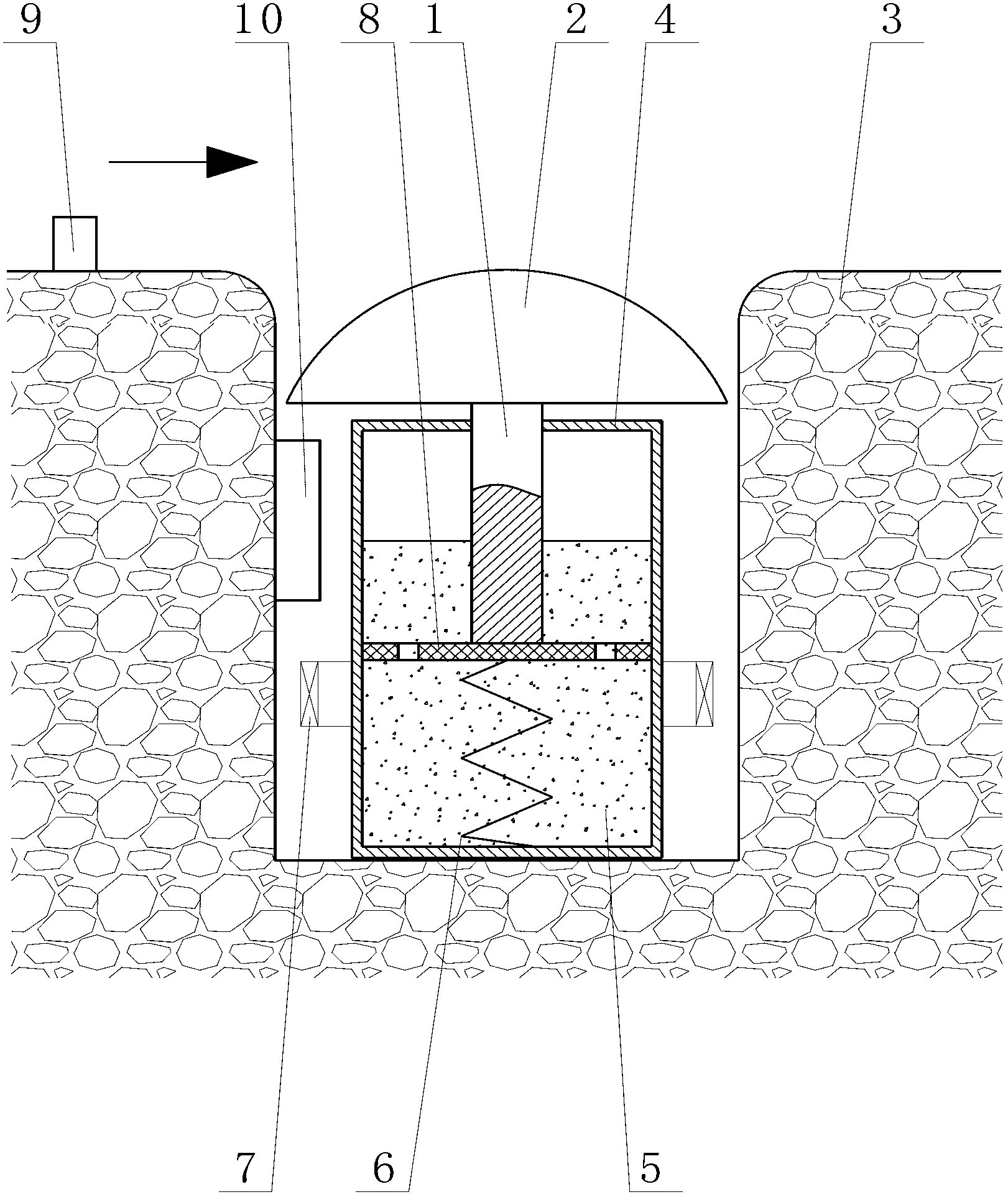
[0035] On the entry side of the speed limit area of ​​lane 3, at least one square long slot is set up perpendicular to the length direction of lane 3. , the piston 8 that moves vertically down, at least six through holes 801 are provided on the piston 8, the cylinders on the upper and lower sides of the piston 8 are connected, and the spring 6 is elastically pressed between the bottom wall of the cylinder and the piston 8, and the spring 6 two ends are in contact with the bottom wall of the cylinder body and the bottom of the piston 8 respectively.

[0036] The cylinder below the piston 8 is filled with the magnetorheological fluid 5, and the electromagnetic coil 7 is arranged around the magnetorheological fluid 5 in the long groove cavity. The electromagnetic coil 7 is connected to the power supply through the power control switch circuit, and the power control switch sign...


PUM


Abstract

Disclosed is a magnetorheological fluid speed bump. At least one rectangular channel is arranged in a direction perpendicular to the lane length direction on the entry side of a lane speed zone. A piston cylinder is disposed in each channel; a piston in the piston cylinder is provided with through holes; a spring is elastically compressed between the bottom wall of a cylinder block and the piston; the cylinder block is full of magnetorheological fluid below the piston; a solenoid coil is disposed around the magnetorheological fluid in a cavity of the channel; a piston rod at the top of the piston upwardly penetrates through the top of the cylinder block of the piston cylinder, and a speed bump is fixed at the top of the penetrating end; the speed bump covers an opening of the channel; the speed bump can horizontally move up and down in the channel. A speedometer is installed on the lane on the entry side of the speed bump and is in signal connection with an electric control unit. The rigidity of the speed bump is flexibly variable, rigid contact and stress between the speed bump and vehicles can be reduced within an allowable speed range, the vehicles and the speed bump are protected effectively, driving comfort is improved, and the speed of the vehicle exceeding the allowable speed range can be limited effectively.

Description

technical field [0001] The invention relates to the field of traffic safety facilities, in particular to a speed-adjusting deceleration belt. Background technique [0002] Speed ​​bumps are also called speed bumps, which are traffic facilities installed on the road to slow down passing vehicles. They are generally strip-shaped or dot-shaped, and the material is mainly rubber or metal. Generally, they are yellow and black to cause visual acuity. Note that the road surface is slightly arched to achieve the purpose of vehicle deceleration. It is generally set at highway crossings, industrial and mining enterprises, schools, residential quarter entrances, etc., where vehicles need to slow down and road sections that are prone to traffic accidents. New traffic-specific safety settings for non-motorized vehicle speeds. The speed bump has greatly reduced the occurrence of accidents at major traffic intersections, and is a new type of special facility for traffic safety. [0003] ...

Claims


Application Information

Patent Timeline
IPC IPC(8): E01F9/047E01F9/529
Inventor 任洪娟罗一平王汇龙马其华王孝兰
Owner SHANGHAI UNIV OF ENG SCI
Why Eureka
Try Eureka