
Crankcase ventilation oil returning structure

A crankcase ventilation and crankcase technology, applied in crankcase ventilation, engine components, machines/engines, etc., can solve the problems of increasing the burden on the oil and gas separation system, increasing the degree of oil atomization, and reducing weight and fuel consumption. Effect

Inactive Publication Date: 2013-04-24
CHONGQING CHANGAN AUTOMOBILE CO LTD
View PDF6 Cites 5 Cited by
  • Summary
  • Abstract
  • Description
  • Claims
  • Application Information

AI Technical Summary

Problems solved by technology

When the engine is working, in this channel, the engine oil flows from top to bottom, and the blow-by gas of the piston moves from bottom to top, which will increase the degree of atomization of the engine oil and increase the burden on the oil-gas separation system

Method used


Image

  • Crankcase ventilation oil returning structure
  • Crankcase ventilation oil returning structure
  • Crankcase ventilation oil returning structure

Examples


Embodiment Construction

[0015] The present invention will be further described below in conjunction with accompanying drawing.

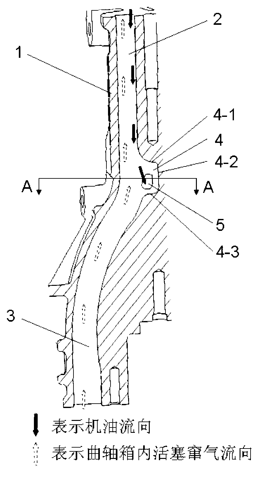
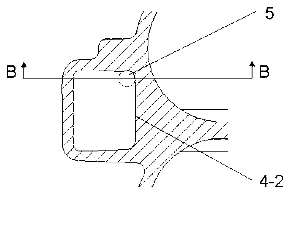
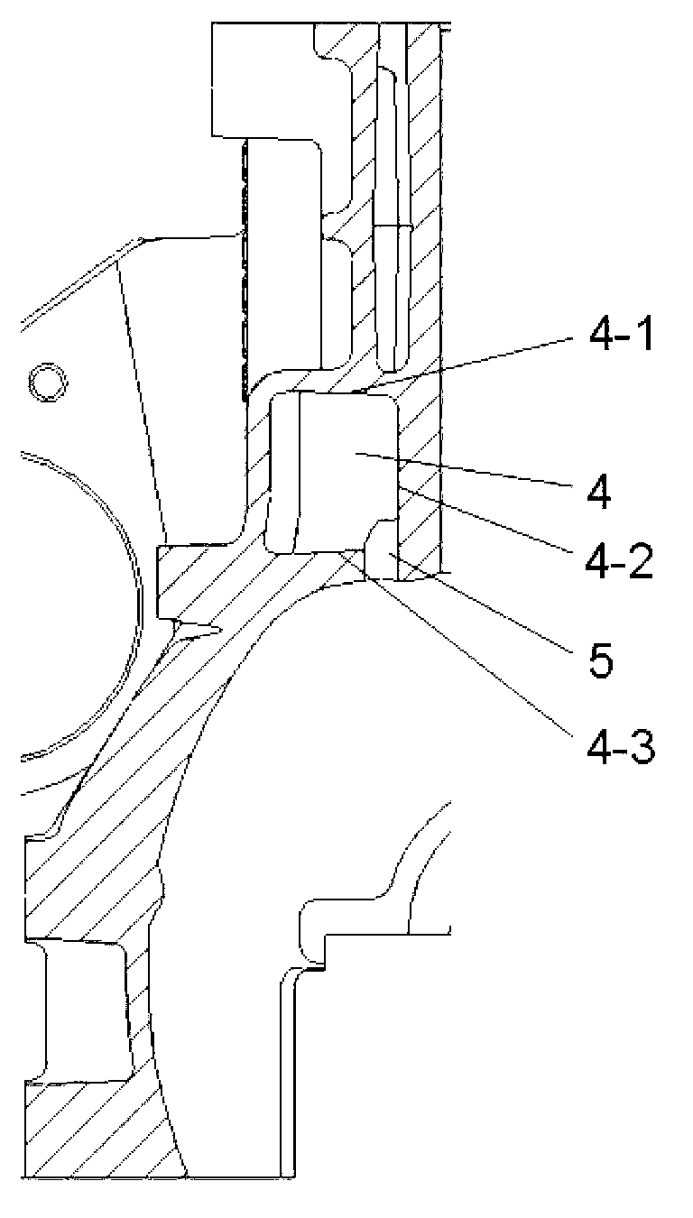
[0016] see figure 1 , a crankcase ventilation oil return structure, comprising a crankcase body 1 and a crankcase chamber in the crankcase body, a ventilation oil return passage is arranged on the crankcase body, and the ventilation oil return passage includes an upper section of the ventilation oil return passage 2 and the lower section 3 of the ventilation oil return channel, a groove 4 is arranged on the inner side of the channel at the junction of the upper section and the lower section of the channel, and an oil return hole 5 communicating with the crankcase chamber is opened in the groove.

[0017] see figure 1 , when the engine is working, in the ventilation oil return channel, the piston blow-by gas moves from bottom to top, through the channel upwards into the oil-gas separation system, the oil flows from top to bottom, when the oil flows to the end of the upper s...


PUM

PropertyMeasurementUnit
Diameteraaaaaaaaaa

Abstract

A crankcase ventilation oil returning structure comprises a crankcase body. A ventilation oil returning channel is arranged on the crankcase body and comprises a ventilation oil returning channel upper section and a ventilation oil returning channel lower section, a groove is arranged on the inner side of the channel between the upper section and the lower section, and an oil returning hole communicated with a crankcase chamber is arranged in the groove. The crankcase ventilation oil returning structure can ensure that piston blow-by passes through the crankcase channel and can be smoothly led into an oil-gas separation system upward, engine oil passes through the channel and can smoothly return when returns back, atomized engine oil is decreased, burden of the oil-gas separation system is lightened, and engine oil consumption is reduced.

Description

technical field [0001] The invention relates to the technical field of engines, in particular to an engine crankcase ventilation oil return structure. Background technique [0002] With the development of society, the number of automobiles has been greatly increased year by year, and the problems of environmental pollution and energy crisis caused by automobiles have become more and more serious, and there are more stringent requirements for automobile engine emissions and fuel consumption. Generally speaking, the oil mist generated by the oil in the engine will be taken by the piston blow-by gas in the crankcase to the oil-air separation system for separation. If the oil return is not smooth or the ventilation is poor, the oil mist will be too thick. When the load of the oil-air separation system is exceeded, some engine oil will enter the combustion chamber through the intake manifold for combustion, which will cause serious problems of excessive oil consumption and excess...

Claims


Application Information

Patent Timeline
IPC IPC(8): F01M13/04
Inventor 徐丽茹徐勇王亚鹏李久林吴先非
Owner CHONGQING CHANGAN AUTOMOBILE CO LTD
Learn More