Air-cooled intercooler

An air-cooled and cooler technology, applied in the direction of machines/engines, internal combustion piston engines, mechanical equipment, etc., can solve the problems of large flow resistance of spoilers with variable tooth width, weak heat dissipation capacity of corrugated fins, etc., and achieve compact structure , long service life, and the effect of improving air intake efficiency

Inactive Publication Date: 2013-04-24
SOUTH CHINA UNIV OF TECH
View PDF7 Cites 6 Cited by
  • Summary
  • Abstract
  • Description
  • Claims
  • Application Information

AI Technical Summary

Problems solved by technology

The corrugated fins have weak heat dissipation capability, and the flow resistance of the spoiler with variable tooth width is relatively large. These structures can no longer meet the development requirements of the new era.

Method used


Image

  • Air-cooled intercooler
  • Air-cooled intercooler
  • Air-cooled intercooler

Examples


Embodiment Construction

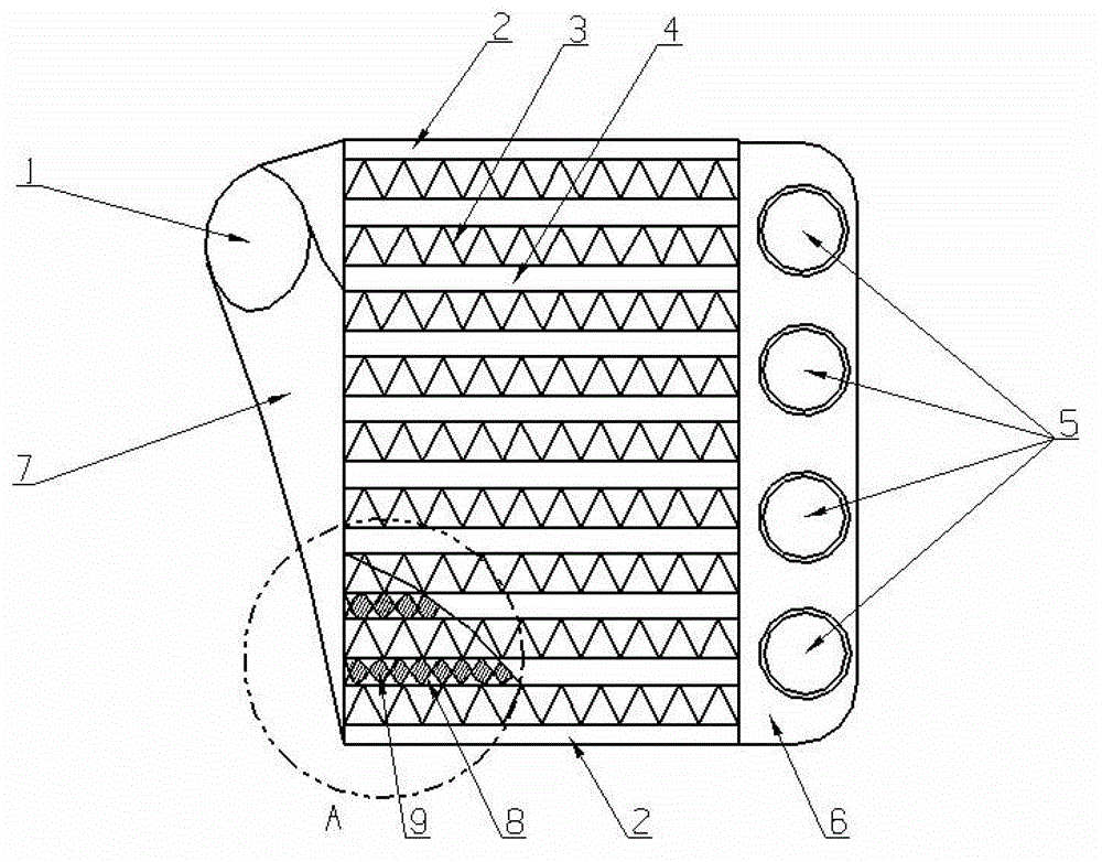
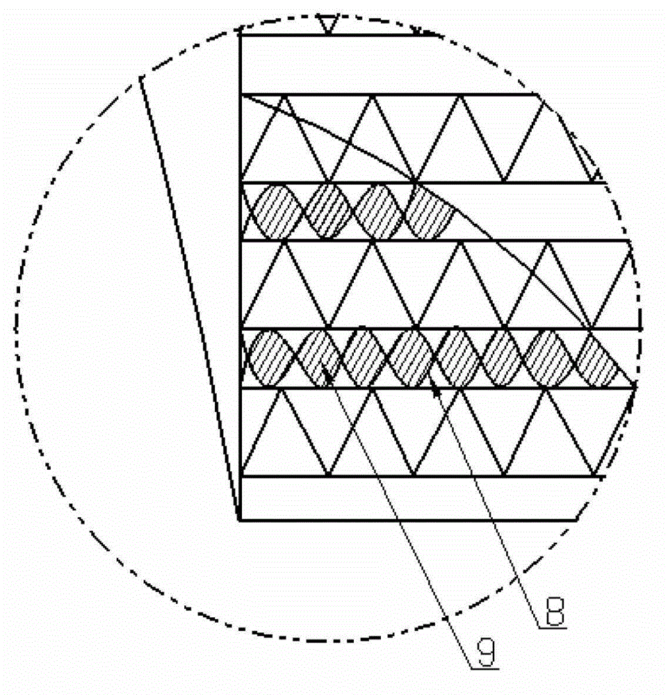
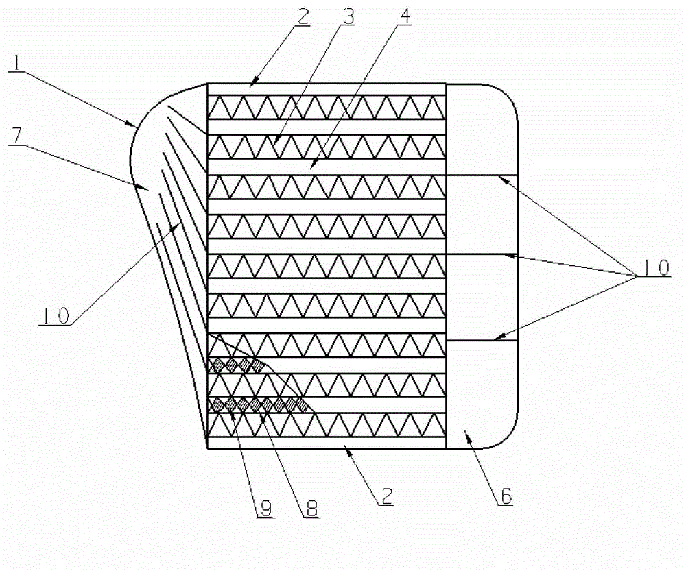
[0030] see Figure 1 ~ Figure 3 , The air-cooled intercooler of the present invention includes a core body and an air inlet 1 and an air outlet 5 connecting the core body. The core body is mainly composed of a side plate 2, an air intake chamber 7, an exhaust chamber 6, a heat dissipation pipe 4, and a heat dissipation fin 3, etc., wherein the side plate 2 includes two upper and lower pieces, which are combined to form a frame of the core body. The air intake chamber 7 and the exhaust chamber 6 are arranged at both ends of the frame, and the heat dissipation pipes 4 and the heat dissipation fins 3 are arranged in the frame.

[0031] see Figure 1 to Figure 6, the radiating pipes 4 are eight, arranged at equal intervals from top to bottom between the upper and lower side plates 2, the two ends of each radiating pipe 4 communicate with the air intake chamber 7 and the exhaust chamber 6 respectively, and the radiating pipes 4 are Flat tube with a height of 7mm. Each heat pipe ...


PUM


Abstract

The invention discloses an air-cooled intercooler which comprises a core. The core comprises an air inlet chamber, an air outlet chamber, a radiating tube and a radiating fin, two ends of the radiating tube are respectively communicated with the air inlet chamber and the air outlet chamber, and a spoiler is arranged in the radiating tube. An air inlet and an air outlet are respectively connected onto the air inlet chamber and the air outlet chamber, the spoiler is of deoxyribose nucleic acid (DNA) duplex structure, and the spoiler is formed by two frameworks of the duplex structure and a bond-shaped fin connected between the two frameworks. The air-cooled intercooler is provided with the spoiler of the DNA duplex structure and has the advantages of good heat transfer effects and small flow resistance.

Description

technical field [0001] The invention relates to an intercooler in a turbocharged diesel engine, in particular to an air-cooled intercooler. Background technique [0002] One of the most important tasks of modern automobiles in terms of internal combustion engines is to reduce fuel consumption and the emission of harmful substances while increasing the power per unit volume. To achieve this goal, the most effective way is to use supercharging. Most of the supercharging technologies use turbocharging, but the speed of the turbocharger can be as high as hundreds of thousands of revolutions, and the density of the air will increase during the process of being compressed, which will inevitably lead to an increase in the temperature of the air, thus Affects the charging efficiency of the engine. If you want to further improve the charging efficiency, you need to reduce the intake air temperature. Some data show that under the same air-fuel ratio conditions, the engine power can...

Claims


Application Information

Patent Timeline
Patent Type & Authority Applications(China)
IPC IPC(8): F02B29/04
CPCY02T10/146Y02T10/12
Inventor 简弃非马广青
Owner SOUTH CHINA UNIV OF TECH
Why Eureka
Try Eureka