Internally ventilated brake disk

A technology of brake discs and brake linings, applied in the direction of brake discs, brake types, brake components, etc., can solve problems such as lining wear and noise, improve stability, avoid dirt, and improve mechanical stability sexual effect

Inactive Publication Date: 2013-04-24
AUDI AG
View PDF7 Cites 4 Cited by
  • Summary
  • Abstract
  • Description
  • Claims
  • Application Information

AI Technical Summary

Problems solved by technology

In addition, achieving uniform lining wear in such brake discs is problematic and can also create noise problems

Method used


Image

  • Internally ventilated brake disk
  • Internally ventilated brake disk
  • Internally ventilated brake disk

Examples


Embodiment Construction

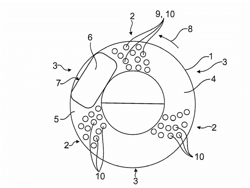
[0024] figure 1 A simplified diagram showing an internally ventilated brake disc 1 with a friction ring 4 divided into perforated segments 2 and unperforated segments 3 , through which brake linings 6 pass during braking The bottom surface / foot surface 7 , which is not visible here, bears against the visible friction surface 5 of the friction ring. On the non-visible rear friction ring of the brake disc 1 lies the opposite brake lining, also not visible here. The bottom surface 7 lies almost completely inside the unperforated segment 3 , so that maximum braking force can be achieved. If the brake disc is rotated further in the direction of rotation 8 , the holes 9 of the segment 2 passing under the brake lining 6 sweep over the bottom area 7 of the brake lining 6 . For the sake of simplicity, only a few of said holes are designated with reference numeral 9 . The remaining perforated segments 2 have corresponding holes, which can be through-holes 10 .

[0025] The holes pro...


PUM


Abstract

An internally ventilated brake disk includes friction rings (4, 14) arranged on both sides. Each friction surface of the friction rings engages with a base surface (7) of a brake pad (6) during braking. Cooling channels (13) extend between the friction surfaces and leading to cooling channel openings (15) disposed on a peripheral edge of the brake disk (1). The friction rings (4, 14) comprise through holes (10) extending to the cooling channels (13) from the friction surfaces (5). The through-holes (10) in perforated fan-shaped segments of the friction rings (4, 14) are distributed in the fan-shaped surfaces. Unperforated fan-shaped segments are disposed between the perforated fan-shaped segments (2).The fan-shaped surface of each unperforated segment extends at least over half the base surface (7) of the contacting brake pad (6).

Description

technical field [0001] The invention relates to an internally ventilated brake disc according to the preamble of claim 1 . Background technique [0002] Internally ventilated brake discs are known which have cooling channels formed between two friction rings. As the rotational speed increases, a correspondingly high air flow rate occurs in the cooling ducts, thereby cooling the brake discs. [0003] In order to suck out the brake dust falling on the friction surface of the friction ring of the internally ventilated brake disc through the cooling channel, US 7 097 007 B2 stipulates that an additional through-slit is formed in the friction surface of the friction ring slot. The through-slit leads to a cooling channel formed between the friction rings, whereby brake dust in the area of ​​the friction surface can be sucked out via the slot and due to the negative pressure prevailing in the cooling channel. In this known brake disc, the grooves with additional through-slits ar...

Claims


Application Information

Patent Timeline
Patent Type & Authority Applications(China)
IPC IPC(8): F16D65/12F16D65/847
CPCF16D65/12F16D65/847F16D2069/004F16D2065/1328
Inventor C·亨奇克
Owner AUDI AG
Why Eureka
Try Eureka