An automatic deflection measuring device and its measuring method

An automatic measurement and force sensor technology, applied in the field of deflection measurement research, can solve the problems that the accuracy is difficult to meet the requirements of bridge deflection measurement, the accuracy and linearity cannot be satisfied, and it is difficult to meet the accuracy requirements, etc., to achieve simple structure and stable measurement data , a wide range of effects

Active Publication Date: 2016-05-04
SOUTH CHINA UNIV OF TECH
View PDF13 Cites 0 Cited by
  • Summary
  • Abstract
  • Description
  • Claims
  • Application Information

AI Technical Summary

Problems solved by technology

However, in the current use process, the device using this method also has certain shortcomings, such as the patent No. 01209421.8, which uses a straight pipe to install a ruler for manual reading, so the accuracy of this instrument is not more than 1mm
As for those that use photoelectric sensors for reading, such as patents with patent numbers 200320127308.X and 200420013598.X, due to the influence of water surface tension and no amplification function, their accuracy and stability are also doubtful.
In addition, these patents with patent numbers of 201120026894.3, 200810237453.0, 200810237454.5, 200910273439.0, and 200920005141.7 all use micro-pressure sensors or pressure transmitters to measure the water column pressure, because the water column pressure changes extremely small, and the connector after multiple pipes divide the pressure , the water pressure is smaller, so it is difficult to achieve the ideal accuracy requirements
There is also the use of buoyancy or floats to convert liquid level displacements, through elastic elements or photoelectric sensors to sense buoyancy changes or float displacements such as 201110204309.9, 201120258359.0, this method has the problem of secondary conversion, and there are also problems such as friction and verticality of the float. Therefore, its accuracy and linearity cannot meet the requirements of existing applications.
[0007] It can be seen that since the liquid level displacement, pressure or buoyancy are not amplified, and these quantities are directly measured, even if a very precise grating sensor, photoelectric sensor or micro-pressure sensor is used, its accuracy is difficult to meet the requirements of bridge deflection measurement

Method used


Image

  • An automatic deflection measuring device and its measuring method
  • An automatic deflection measuring device and its measuring method
  • An automatic deflection measuring device and its measuring method

Examples


Embodiment 1

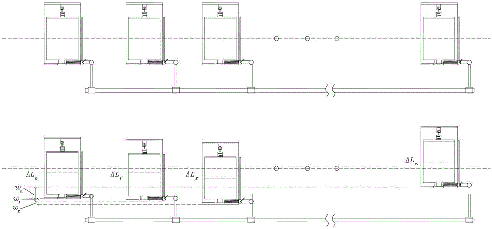
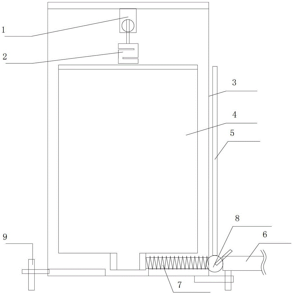
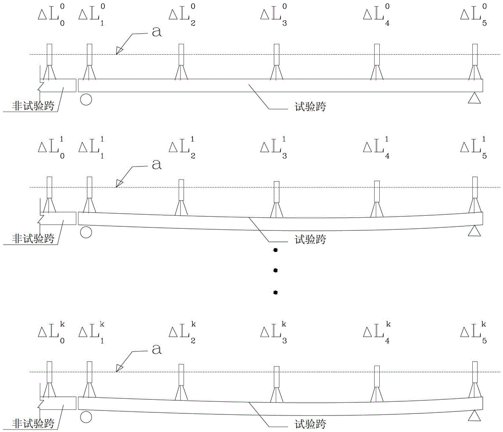
[0041] This embodiment uses multi-point measurement of bridge deflection to illustrate the specific measurement method and measurement device. Such as image 3 As shown, the simple and convenient connecting pipe 15 is laid out, then filled with water, and an elevated block is laid at the measuring point position, placed as figure 2 The shown measuring device 17 makes the initial water surface height of the transparent tube 5 equal to the initial line of the standpipe 4, and balances the vial on the outer frame 3. Turn on the switches of the flexible pipe 7 and the water inlet pipe 6 to allow the vertical pipe 4 in the measuring device to enter water. Connect the sensor signals of various places to the strain gauge and connect it to the computer. At this time, the data can be cleared. When the bridge is loaded, each measuring point will rise or fall, such as figure 1 and 3 As shown, according to the principle of the connector, the liquid level of each measuring tube will d...

Embodiment 2

[0052] This embodiment has the same structure as Embodiment 1 except for the following features: in this embodiment, the device and method of the present invention are applied to measuring elevation or elevation, such as Figure 4 , 5 shown.

[0053] Choose vertical pipes of different lengths according to the total elevation difference of the measured structure (the measuring range needs to be large enough). On a reference point (such as the horizontal plane represented by a in the figure), the measuring device of the present invention is arranged, filled with water, and then another measuring device is installed on a movable mark post 16, which can be provided with a vial ( Or directly use the vial on the measuring instrument). Mark the position of the measuring point in advance according to a certain length (for example, the horizontal position of the measuring point represented by b in the figure), move the benchmark 16 to the measuring point in turn, and read the reading...


PUM


Abstract

The invention discloses a deflection automatic measuring device and measuring method thereof. The deflection automatic measuring device comprises an outer frame, a vertical tube, a flexible tube and a force sensor. The vertical tube is arranged on the midpoint in the outer frame and fixedly connected with the lower end of the force sensor. The upper end of the force sensor is connected with the outer frame through a universal head. A force bearing rod for fixing the universal head is arranged on the upper portion of the outer frame. The universal head is hinged with the force sensor. A water inlet hole is formed in one side of the bottom of the vertical tube and connected with the flexible tube. The flexible tube is horizontally arranged on the bottom frame of the outer frame. The other end of the flexible tube is connected with an outer water inlet tube. A valve for controlling breaking over of the flexible tube is arranged on the joint of the other end of the flexible tube and the outer water inlet tube. The deflection automatic measuring method measures weight variation of liquid in the vertical tube, and the deflection value is obtained according to relationship of the weight variation and structural deflection values. The deflection automatic measuring device and measuring method thereof integrates a communicating tube and strain measurement technique, measurement accuracy is high, can be widely used in vertical displacement measurement in the construction process of building, project, slope protection, foundation pit and the like, and can apply to structural short-term deflection measurement in structural static and dynamic detection.

Description

technical field [0001] The invention relates to the field of deflection measurement research, in particular to an automatic deflection measurement device and a measurement method thereof. Background technique [0002] At present, an important content in the bridge load test is the measurement of the deformation (deflection) of the structure under load, which reflects the stiffness characteristics of the structure. At present, the deflection tests are mainly divided into the following categories: [0003] 1. Level or total station. The principle is to pre-arrange a number of fixed measuring points on the structure, place one point on a certain fixed point or a relatively fixed point, and then use the level to read the height of each tower foot after each loading according to the principle of leveling. Elevation, the deflection at this place can be obtained after subtracting the front and back. The advantage is that it can carry out multi-point measurement, no need to insta...

Claims


Application Information

Patent Timeline
Patent Type & Authority Patents(China)
IPC IPC(8): G01M5/00G01C5/04
Inventor 周希平
Owner SOUTH CHINA UNIV OF TECH
Why Eureka
Try Eureka