
Collecting device for improving small-light monitoring precision and monitor signal collecting method

A collection device and optical signal technology, applied in the field of optical communication, can solve problems such as large sampling error, large monitoring error, and increased monitoring error

Active Publication Date: 2013-04-24
HISENSE BROADBAND MULTIMEDIA TECH
View PDF5 Cites 14 Cited by
  • Summary
  • Abstract
  • Description
  • Claims
  • Application Information

AI Technical Summary

Problems solved by technology

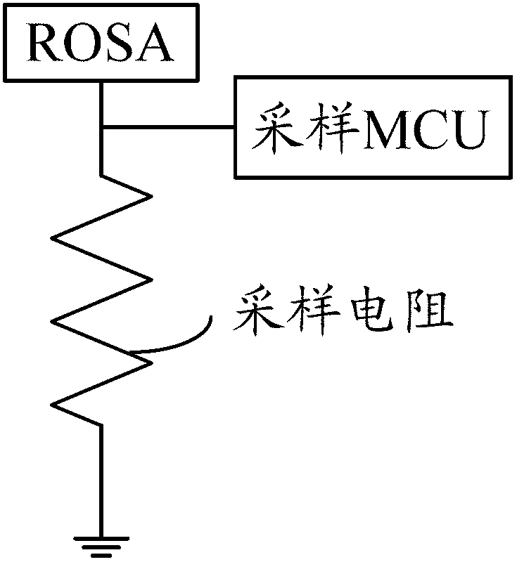
[0016] It can be seen from the above that the existing optical module can monitor the optical monitoring accuracy of the input light by sampling the light, converting the analog to digital, and calculating the optical monitoring accuracy according to the monitoring accuracy calculation formula. However, in practical applications, the input The range of light is wide, for example, up to -37dbm ~ -10dbm, and a single sampling circuit is used to sample the current signal after photoelectric conversion, so that for input light with low optical power, the sampling error is large, thereby increasing monitoring error
For example, when the monitored input light is -30dbm, the monitoring error can reach ±3db, and when the monitored input light is -37dbm, the resulting monitoring error is even greater

Method used


Image

  • Collecting device for improving small-light monitoring precision and monitor signal collecting method
  • Collecting device for improving small-light monitoring precision and monitor signal collecting method
  • Collecting device for improving small-light monitoring precision and monitor signal collecting method

Examples


Embodiment Construction

[0100]In order to make the object, technical solution and advantages of the present invention clearer, the present invention will be described in further detail below with reference to the accompanying drawings and preferred embodiments. However, it should be noted that many of the details listed in the specification are only for readers to have a thorough understanding of one or more aspects of the present invention, and these aspects of the present invention can be implemented even without these specific details.

[0101] As used herein, the terms "unit", "means", "module" and the like are intended to include computer-related entities such as but not limited to hardware, firmware, a combination of hardware and software, software, or software in execution. For example, a module may be, but is not limited to being limited to being, a process running on a processor, a processor, an object, an executable, a thread of execution, a program, and / or a computer. For example, both an ...


PUM


Abstract

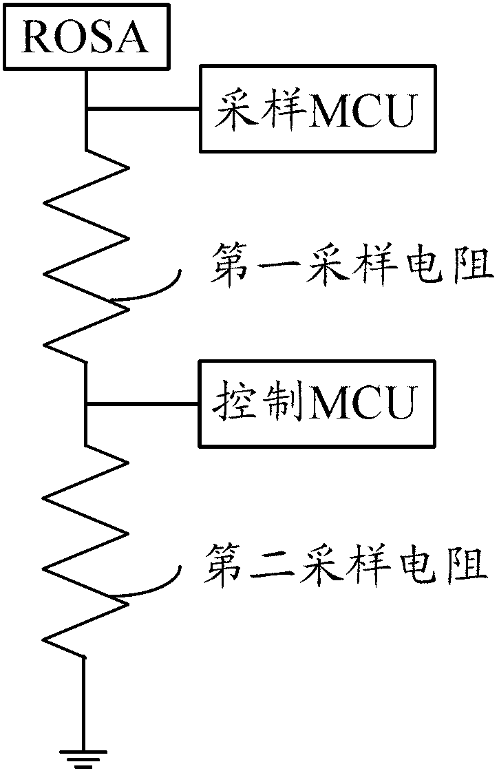
The invention discloses a collecting device for improving a small-light monitoring precision and a monitor signal collecting method. The collecting device for improving the small-light monitoring precision comprises a light-receiving subunit, a sampling micro processing unit, a control micro processing unit, a first sampling resistor and a second sampling resistor, wherein one end of the second sampling resistor is connected with the ground, and the other end of the second sampling resistor is respectively connected with one end of the first sampling resistor and the control micro processing unit; the other end of the first sampling resistor is respectively connected with the sampling micro processing unit and the output of the light-receiving subunit; the control micro processing unit is controlled by a program to output a high impedance state or a low level, the sampling micro processing unit conducts voltage sampling from the first sampling resistor, and sampled voltage is converted into a digital value; and the light-receiving unit is used for outputting monitoring currents in preset proportion to the size of received light. The collecting device for improving the small-light monitoring precision and the monitor signal collecting method can improve monitoring precision when small light is input.

Description

technical field [0001] The invention relates to optical communication technology, in particular to a collection device and a monitoring signal collection method for improving the monitoring accuracy of small light. Background technique [0002] In the current domestic market and international market, optical fiber communication with high bandwidth, high speed and multi-service integration has begun to be applied. Among the many solutions, Synchronous Digital Hierarchy (SDH, Synchronous Digital Hierarchy) / Synchronous Optical Network (SONET, Synchronous Optical Network) technology has been widely used in the domestic market due to the use of optical fiber transmission. Among them, SONET defines the transmission of synchronous and isochronous information, while the SDH optical transceiver has a large capacity, which can integrate multiplexing, line transmission and switching functions, and is an integrated information transmission network operated by a unified network managemen...

Claims


Application Information

Patent Timeline
Patent Type & Authority Applications(China)
IPC IPC(8): H04B10/07
Inventor 樊凤梅丁良云高庭马军涛
Owner HISENSE BROADBAND MULTIMEDIA TECH
Learn More