

Method, application server, network database and system achieving heartbeat mechanism
A technology of application server and heartbeat mechanism
- Summary
- Abstract
- Description
- Claims
- Application Information
AI Technical Summary
Problems solved by technology
Method used
Image

Examples
Embodiment 1
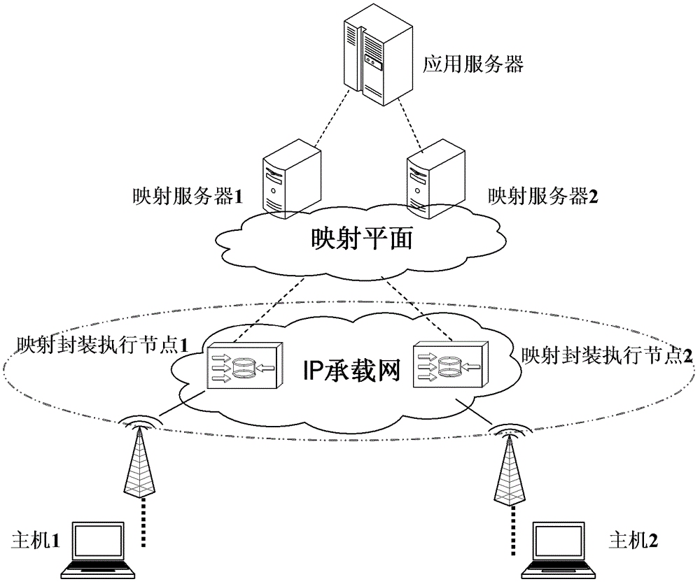
[0138] This embodiment is based on the solution for separating the identity and location of the network router, and describes the specific implementation of the present invention:
[0139] Such as figure 1 As shown, the network elements included in the network-based solution can be logically abstracted into: host, network database, mapping and encapsulation execution node / forwarding device. There are two types of identification for hosts in a network: host identity identification and location routing identification. The host ID indicates the identity of the user, and is used to identify the communication peer during end-to-end communication; the location ID indicates the current location of the end user, and is used for routing when data packets are forwarded. The network database saves the corresponding relationship between the identity identifier and the location identifier of the terminal host through the mapping table.
[0140] The identity remains static as the host acc...
Embodiment 2
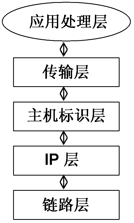
[0163] This embodiment describes the specific implementation of the present invention based on the host identity and location separation solution:
[0164] Such as image 3 As shown, the basic idea of the host-based identity identification and location separation solution is to introduce a host identification layer between the host network layer and the transport layer. The host identification layer separates the original tightly coupled transport layer and the network layer. The IP address no longer plays the role of identifying the host. It is only responsible for the routing and forwarding of data packets, that is, it is only used as a location identifier, and the host name is represented by the host identifier. . The host identification layer is logically located between the network layer and the transport layer, and the host completes the translation of the host identifier and IP address in the data packet. The network layer is shielded from the transport layer, and a...
PUM
 Abstract
Description
Claims
Application Information