Multilear collimator, particle beam therapy device and therapy planning device

A multi-leaf collimator and particle beam technology, which is applied in X-ray/γ-ray/particle irradiation therapy, treatment, radiotherapy, etc., can solve the problem of charged particle beam dose attenuation and other issues

Inactive Publication Date: 2013-04-24
MITSUBISHI ELECTRIC CORP
View PDF8 Cites 20 Cited by
  • Summary
  • Abstract
  • Description
  • Claims
  • Application Information

AI Technical Summary

Problems solved by technology

However, in the case of linearly driving the vane plate, a charged particle beam at an angle to the diffusion direction is irradiated to a part of the end face of the vane plate at a contour portion away from the center of the irradiation field, resulting in continuous occurrence of dose of the charged particle beam. Sexual attenuation, which produces the so-called penumbra

Method used


Image

  • Multilear collimator, particle beam therapy device and therapy planning device
  • Multilear collimator, particle beam therapy device and therapy planning device
  • Multilear collimator, particle beam therapy device and therapy planning device

Examples


Embodiment approach 1

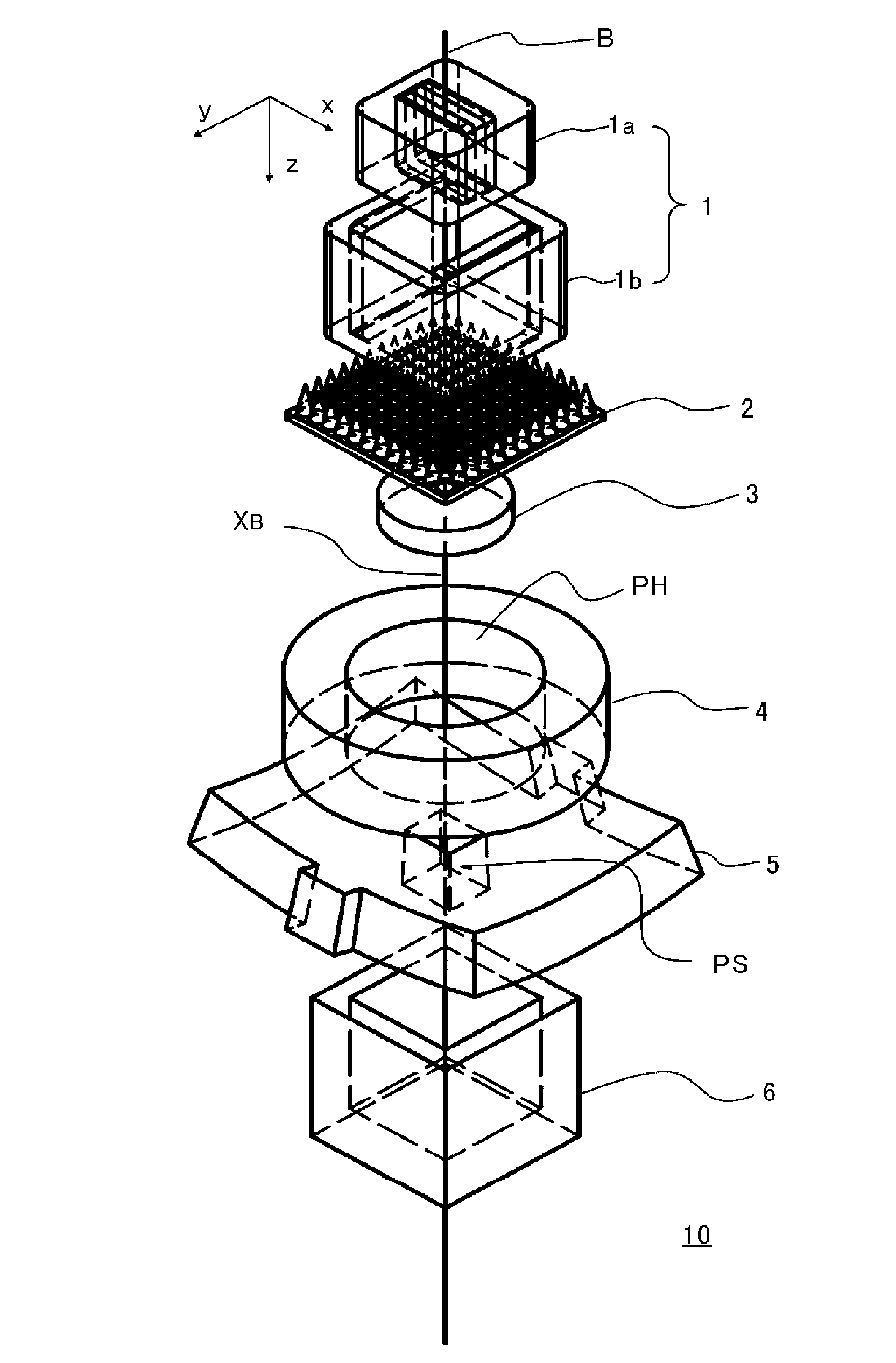
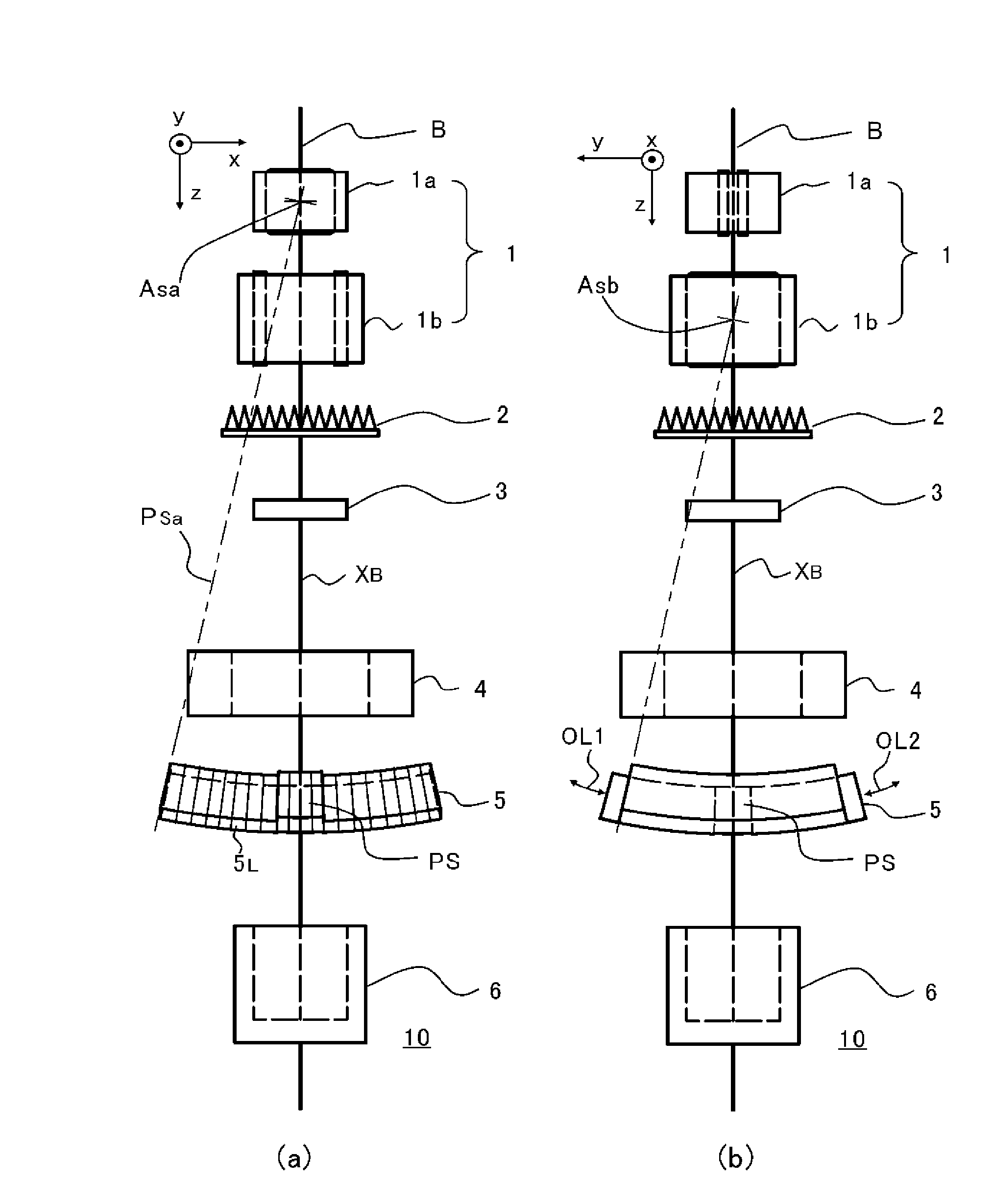
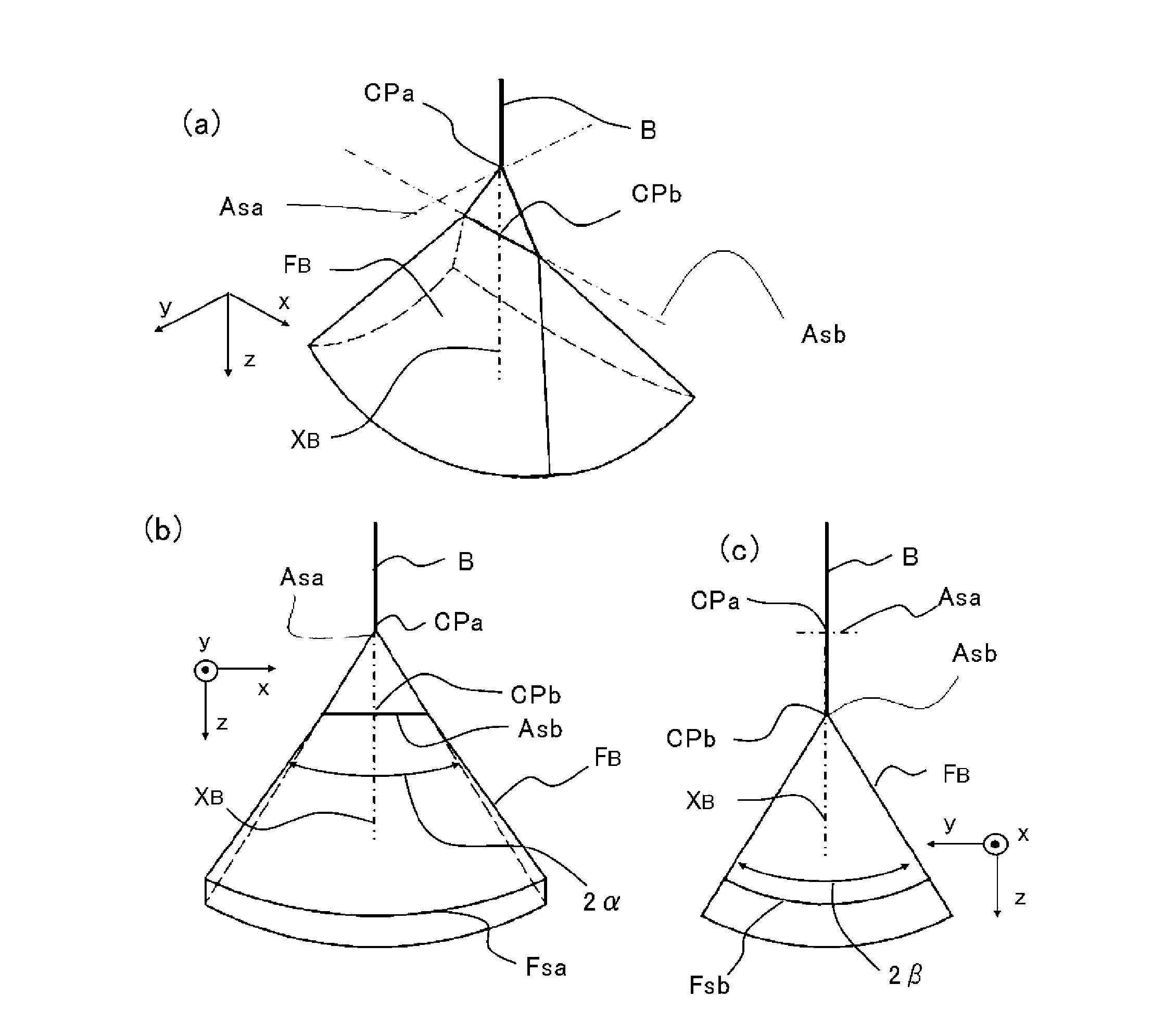
[0030] Next, configurations of the multileaf collimator and the particle beam therapy apparatus according to Embodiment 1 of the present invention will be described. Figure 1 to Figure 5 It is a figure for demonstrating the structure of the multileaf collimator and particle beam therapy apparatus concerning Embodiment 1 of this invention, figure 1 It is a figure showing the structure of the irradiation system of the particle beam therapy apparatus including a multi-leaf collimator, figure 2 In order to show the structure of the particle beam therapy device and the multi-leaf collimator from figure 1 In the diagram observed in the direction perpendicular to the center (z-direction) of the charged particle beam, figure 2 (a) is a side view viewed from the y direction, figure 2 (b) is a side view seen from the x direction. image 3 It is a figure for explaining the shape of the beam in the irradiation system of the particle beam irradiation apparatus, image 3 (a) A diagra...

Embodiment approach 2

[0057] In Embodiment 1, the application of the helical wobble method of scanning the beam in a helical shape was explained. However, the shape of the scanning trajectory (scanning trajectory) of the beam in the irradiation field is not limited to the technical idea of ​​the present invention, and the effect of performing two-stage scanning diffusion can also be exerted in other beam scanning trajectory. Therefore, in Embodiment 2, the case will be explained by applying the multileaf collimator of the present invention to an irradiation system having another typical beam scanning trajectory.

[0058] First, the beam scanning trajectory obtained by the helical wobble method used in Embodiment 1 will be described. As described in Patent Document 3, the spiral scanning trajectory is obtained by Equation (1) including the following three equations.

[0059] (mathematical formula 1)

[0060] r ( t ) = ...

Embodiment approach 3

[0087] In Embodiments 1 and 2 above, the case where irradiation is performed using the swing method has been described. However, as described above, the irradiation method itself is not an essential part of the present invention, nor does it limit the technical idea of ​​the present invention. In a particle beam therapy apparatus, a spot scanning method has been proposed which scans a charged particle beam using a two-stage scanning electromagnet and performs spot irradiation on an irradiated object in a point drawing manner. In the case of spot scanning, the spread of the beam is also two-stage scanning. Therefore, even when a multi-leaf collimator is used for spot scanning, the effect of suppressing the above-mentioned penumbra and forming an irradiation field with high contrast can be exhibited.


PUM


Abstract

The purpose of the invention is to obtain a multileaf collimator and a particle beam therapy device that can form high contrast irradiation fields without being affected by the penumbra. The multileaf collimator is provided with an array of leaves (5C) wherein a plurality of leaf plates (5L) are stacked in the thickness direction with one of the end faces (EL) aligned, and with a leaf plate driving mechanism (5D) that drives the one end face (EL) of each leaf plate (5L) towards or away from the beam axis (XB). For each of the leaf plates (5L), the surface (PL) of said leaf plate that faces the adjacent leaf plate in the thickness direction is formed by a plane (PSa) containing a first axis (ASa) that is on the beam axis (XB). The leaf plate driving mechanism (5D) drives the leaf plates (5L) along a circular orbit (OL) having, as the center, a second axis (Asb) that is on the beam axis (XB) and is perpendicular to the beam axis (XB) and to the first axis (Asa).

Description

technical field [0001] The present invention relates to a multi-leaf collimator, a particle beam therapy device using the multi-leaf collimator, and a treatment planning device for determining the operating conditions of the particle beam therapy device, and the multi-leaf collimator is suitable for using charged particle beams An irradiation field is formed in a particle beam therapy device. Background technique [0002] Particle beam therapy is a method of treatment by irradiating charged particle beams to the affected area as the treatment target to destroy the affected tissue. A particle beam therapy device that accurately controls the irradiation dose and the irradiation range (hereinafter referred to as the irradiation field). Among the particle beam therapy devices, in a so-called wide-area irradiation type particle beam therapy device that uses an irradiation nozzle including a scanning electromagnet such as a swing electromagnet, the irradiation field is enlarged b...

Claims


Application Information

Patent Timeline
Patent Type & Authority Applications(China)
IPC IPC(8): A61N5/10
CPCA61N2005/1087G21K1/046A61N5/1042A61N2005/1095A61N5/103A61N5/1043A61N5/1045A61N2005/1096
Inventor 岩田高明
Owner MITSUBISHI ELECTRIC CORP
Why Eureka
Try Eureka