Section steel straightening device and method
A profile and straightening technology, which is applied in the field of profile straightening devices, can solve problems such as the difference in rail height between the blind area of rail straightening and the straightening area, the bending of profiles exceeding the requirements of national standards, and the straightening direction of side bending. Reduce rail height difference, better straightening effect, and better section size of profiles
- Summary
- Abstract
- Description
- Claims
- Application Information
AI Technical Summary
Problems solved by technology
Method used
Image
Examples
Embodiment 1
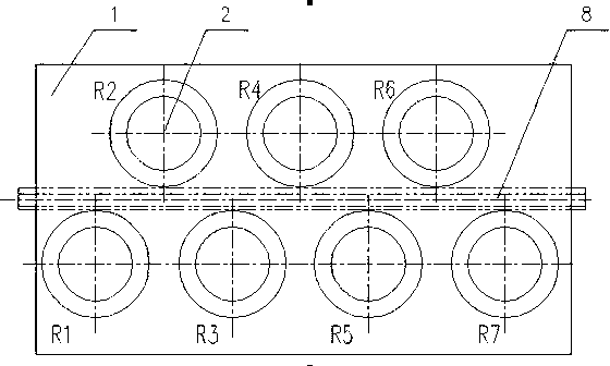
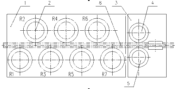
[0030] Such as image 3 Shown is the structural representation of the first embodiment of the profile straightening device of the present invention; as Figure 4 shown as image 3 The side view of the profile straightening device of the present invention includes a straightening roller system 1 arranged on the machine body, and a rolling straightening roller system 3 is also provided at the output end of the straightening roller system 1, and the rolling straightening roller system 3 includes at least one pair The upper and lower rolling and straightening rolls 4, 5 and at least one pair of left and right rolling and straightening rolls 6, 7, the upper and lower rolling and straightening rolls 4, 5 are symmetrically arranged on the upper and lower sides of the steel wire 8 and form a roll between the two rolls to allow the profile to pass Seam I, the left and right rolling and straightening rolls 6, 7 are symmetrically arranged on the left and right sides of the passing steel...
Embodiment 2
[0036] Such as Figure 5 Shown is the structural representation of the first embodiment of the profile straightening device of the present invention; as Figure 6 shown as Figure 5 The side view; the difference between this embodiment and the first embodiment is that the straightening roller system 1 is composed of no less than 3 horizontal rollers 2 arranged staggered on the upper and lower sides of the steel wire and no less than 3 staggered rollers Composed of vertical rollers 10 on the left and right sides of the steel wire, the preferred horizontal rollers 2 are set to 7 and are arranged in turn as R1, R2, R3, R4, R5, R6, R7, and the preferred vertical roller group 10 is set to 7 And it is set as r1, r2, r3, r4, r5, r6, r7 in turn. This embodiment is mainly used for straightening high-speed rails with higher requirements for straightness, residual stress and fracture toughness than ordinary rails. Compared with one, the straightening effect is better.
[0037] Further...
Embodiment 3
[0040] Such as Figure 7Shown is the structural representation of the third embodiment of the profile straightening device of the present invention; as Figure 8 shown as Figure 7 side view. The profile straightening device in this embodiment includes a straightening roller system 1 arranged on the machine body. The straightening roller system 1 is composed of no less than 3 horizontal rollers 2 arranged alternately on the upper and lower sides of the steel wire and no less than It consists of three vertical rolls 10 arranged staggeredly on the left and right sides of the steel wire. In the straightening roll system 1, the output end of the horizontal roll group 2 is provided with a rolling straightening roll system I11. The rolling straightening roll system I11 includes at least one pair of upper and lower rollers. Rolling and straightening rolls 4, 5, the upper and lower rolling and straightening rolls 4, 5 are symmetrically arranged on the upper and lower sides of the st...
PUM
 Abstract
Description
Claims
Application Information
 - R&D
- Intellectual Property
- Life Sciences
- Materials
- Tech Scout
- Unparalleled Data Quality
- Higher Quality Content
- 60% Fewer Hallucinations
Browse by: Latest US Patents, China's latest patents, Technical Efficacy Thesaurus, Application Domain, Technology Topic, Popular Technical Reports.
© 2025 PatSnap. All rights reserved.Legal|Privacy policy|Modern Slavery Act Transparency Statement|Sitemap|About US| Contact US: help@patsnap.com


