Hydraulic volume control forming device for metal corrugated pipe

A metal bellows, volume control technology, applied in the field of bellows manufacturing, can solve the problems of no clear reference index for adjusting the expansion pressure, unable to meet the actual needs of product quality, poor consistency of the wave height and wave distance of the bellows, etc. Achieve stable and reliable product quality, low cost and high waveform consistency

Active Publication Date: 2013-05-01
吕季明 +1
View PDF6 Cites 2 Cited by
  • Summary
  • Abstract
  • Description
  • Claims
  • Application Information

AI Technical Summary

Problems solved by technology

There are two problems in the hydraulic expansion type currently on the market. One is that the inner wall of the steel pipe is used for sealing. The sealing ring has a pre-compression amount, and the front end of the steel pipe needs to be belled.
Second, due to the differences in steel pipe diameter, wall thickness and material, there is no clear reference index for adjusting the expansion pressure, and it is difficult to adjust the expansion pressure, so that the consistency of the wave height and wave distance of the bellows is poor, and the quality of the bellows is poor.
The corrugation forming of metal bellows is a key process for manufacturing metal bellows. These commonly used processes for manufacturing metal bellows cannot meet the actual needs of product quality.

Method used


Image

  • Hydraulic volume control forming device for metal corrugated pipe
  • Hydraulic volume control forming device for metal corrugated pipe
  • Hydraulic volume control forming device for metal corrugated pipe

Examples


Embodiment Construction

[0018] Embodiments of the present invention will be further described below in conjunction with the accompanying drawings.

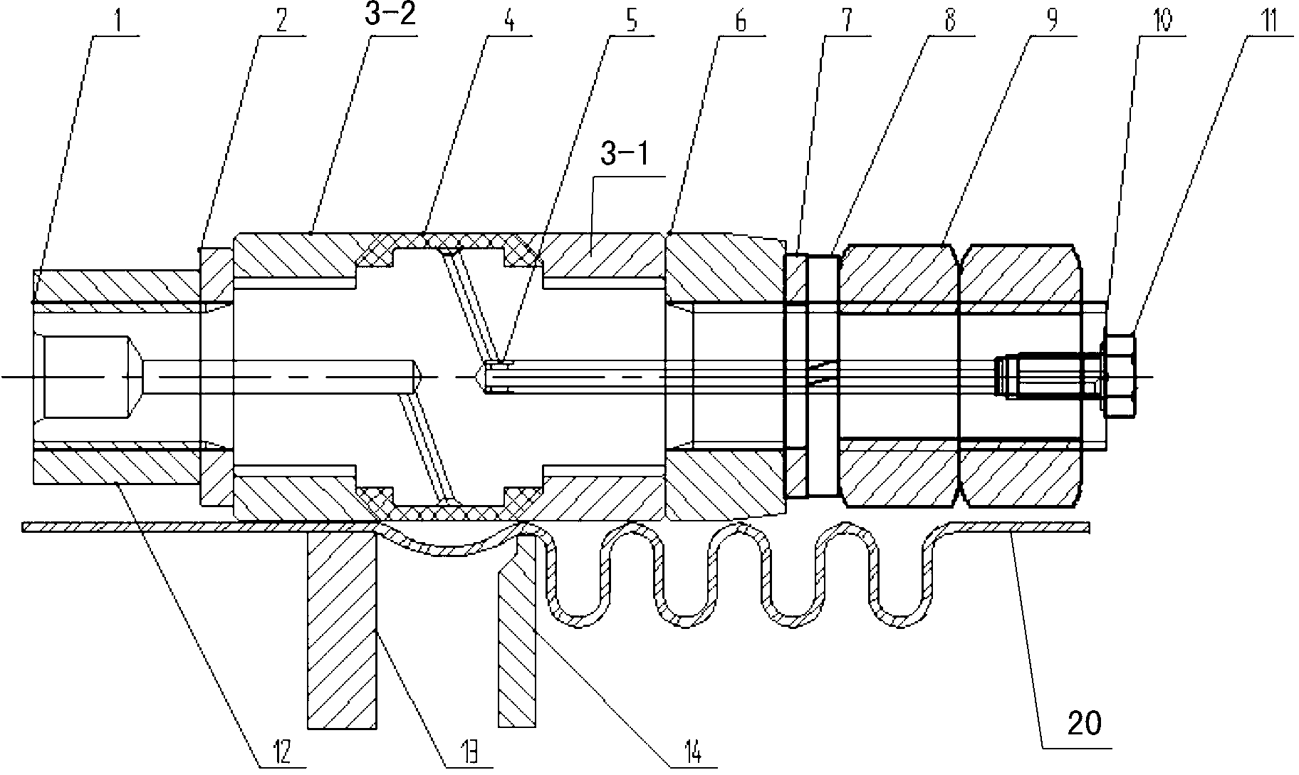
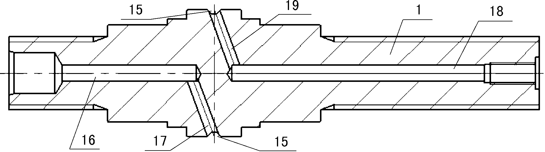
[0019] refer to Figure 1-Figure 4 , taking the axial direction of the mandrel 1 as the reference, the direction close to the air release bolt 11 is forward and forward, and the direction away from the air release bolt 11 is backward and retreat.

[0020] A metal bellows hydraulic volume control molding device, which includes a mandrel 1, the mandrel 1 is provided with two shoulders, and a circular groove 15 is formed on the surface of the highest shoulder section along the axial direction, so that Both ends of the mandrel 1 are threaded, the rear of the mandrel 1 is provided with an oil passage 16, and the front end of the oil passage 16 communicates with the circular groove 15 through the side oil passage 17. The front part is provided with a ventilation pipeline 18, and the rear end of the ventilation pipeline 18 communicates with the circular groove...


PUM


Abstract

The invention relates to a hydraulic volume control forming device for a metal corrugated pipe. The hydraulic volume control forming device for the metal corrugated pipe comprises a mandrel, wherein the surface of the mandrel is provided with a circular slot; the rear part of the mandrel is provided with an oil line; the front end of the oil line is communicated with the circular slot via a side oil passage; the middle front part of the mandrel is provided with a vent line; the rear end of the vent line is communicated with the circular slot via a side vent line; the front end of the vent line is provided with an O-shaped sealing ring and a bleed screw; the circular slot is provided with a capsule; two ends of the capsule are respectively compressed by a rear pressing sleeve and a front pressing sleeve; the rear end of the rear pressing sleeve is successively provided with a washer and a sleeve shaft from front to back; the front end of the front pressing sleeve is successively provided with a taper sleeve, a flat washer, a spring washer and a hexagon nut from back to front; the rear lower end of the capsule is provided with a forming chuck; and the front lower end of the capsule is provided with a matrix. The corrugated pipe manufactured by the hydraulic volume control forming device disclosed by the invention has the advantages of high quality and high waveform consistency.

Description

technical field [0001] The invention relates to the field of bellows manufacturing, in particular to a metal bellows hydraulic volume control forming device. Background technique [0002] Metal bellows are gradually being used in automobile exhaust systems, mainly for connection, compensation, noise reduction, shock absorption and other functions. [0003] At present, the commonly used forming methods for metal bellows are: rubber forming, mechanical forming, and hydraulic expansion. Rubber molding is a kind of bulging process. It uses rubber as a forming punch. Under pressure, the rubber punch is deformed, and the tube blank is expanded and pressed into the concave mold cavity to form a bellows. Rubber molding equipment is simple, fast molding, and no sealing requirements. However, during the two-way rubber extrusion process, the rubber ring may produce axial displacement, which drives the steel pipe to move, so that the consistency of the wave height and wave pitch of th...

Claims


Application Information

Patent Timeline
IPC IPC(8): B21D15/12
Inventor 廖义德吕季明方自明
Owner 吕季明
Why Eureka
Try Eureka