
Floor board cast-in-situ method

A floor and cast-in-place technology, which is applied to floors, building components, buildings, etc., can solve the problems of reducing the overall strength of the building and the inability to form a criss-cross connection into a meshed steel structure, so as to improve the seismic performance of the building and avoid the support of the bottom formwork. Mold work, the effect of ensuring the overall strength of the building

Inactive Publication Date: 2015-07-15
吴涛
View PDF5 Cites 0 Cited by
  • Summary
  • Abstract
  • Description
  • Claims
  • Application Information

AI Technical Summary

Problems solved by technology

However, when the existing prefabricated panels are laid and installed, they cannot form a criss-cross and networked steel structure, which greatly reduces the overall strength of the building, so it has been abandoned in modern building construction.

Method used


Image

  • Floor board cast-in-situ method
  • Floor board cast-in-situ method
  • Floor board cast-in-situ method

Examples


Embodiment Construction

[0019] The present invention will be described in further detail below in conjunction with the accompanying drawings.

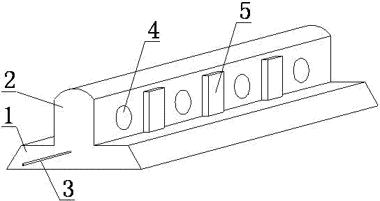
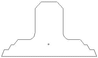
[0020] Such as figure 1 As shown, a floor floor cast-in-place method, first obtain the prefabricated part with the following structure, the prefabricated part is in the shape of a long strip as a whole, including a flat bottom plate part 1 and at least one convex part located above the bottom plate part 1 and arranged along the length direction Ridge 2, the prefabricated part is buried with reinforcing bars 3 along the length direction, the two ends of the reinforcing bar 3 have reserved sections extending out of the prefabricated part, and the ribs 2 are provided with a number of through holes 4 extending horizontally through the ribs along the length direction at intervals along the width direction . Protrusions 5 extending laterally outward are also provided on both sides between adjacent through holes 4 on the rib 2 . The cross-section of the upper surf...


PUM


Abstract

The invention discloses a floor board cast-in-situ method, which is characterized by firstly acquiring a prefabricated member, wherein the prefabricated member comprises a flat soleplate part and at least one bead which is arranged above the soleplate part and arranged in the length direction, a reinforcing steel bar is embedded inside the prefabricated piece along the length direction, two ends of the reinforcing steel bar are provided with a reserved section extending out of the prefabricated piece, and the bead is provided with a plurality of through holes at intervals in the length direction which penetrate through the bead along the width direction; and during the pouring construction, the soleplate parts of a plurality of prefabricated members are downwards connected with each other and placed among leveled vertical walls, a side template flange is respectively installed on the periphery of the prefabricated member, and secondary concrete is poured inside a side template, so that the prefabricated members are connected into a whole to form a floor board structure. The floor board cast-in-situ method is used for producing a building floor board in building construction. Due to the adoption of the method, the complex die-block supporting work can be avoided, the construction cost can be reduced, and the construction time can be reduced; and meanwhile, the method also has the advantages that the integral strength of the building can be guaranteed, and the safety of the building can be improved.

Description

technical field [0001] The invention relates to a building construction method, in particular to a floor floor cast-in-place method. Background technique [0002] At present, the method of cast-in-place formwork is generally used in the construction of buildings in China. When the formwork is cast-in-place, it is necessary to use formwork to support on-site to form a model, and then pour concrete into the model for curing and forming. [0003] This mold-in-place method can embed criss-cross steel bars during pouring, which maintains the integrity of the building and improves the overall strength of the building. However, the cast-in-place method is a complex and changeable large-scale process when the formwork is poured. It requires a large number of molds, complex formwork, and takes a long time for construction and pouring. The disadvantage of long time. At the same time, this mold-in-place method makes it difficult to accurately locate and pre-tension the steel bars use...

Claims


Application Information

Patent Timeline
Patent Type & Authority Patents(China)
IPC IPC(8): E04G21/00E04B5/23
Inventor 吴涛吴应武
Owner 吴涛
Learn More