Combined construction structure

A technology of building structure and keel, applied in building components, building structure, construction and other directions, can solve the problems of increased consumption, complex process and high cost

Active Publication Date: 2013-05-01
深圳市华汇设计有限公司
View PDF9 Cites 15 Cited by
  • Summary
  • Abstract
  • Description
  • Claims
  • Application Information

AI Technical Summary

Problems solved by technology

The aluminum alloy profile of this heat-insulating broken bridge structure has complicated process and high cost, because the first aluminum alloy profile and the second aluminum alloy profile o...

Method used


Image

  • Combined construction structure
  • Combined construction structure
  • Combined construction structure

Examples


Embodiment 1

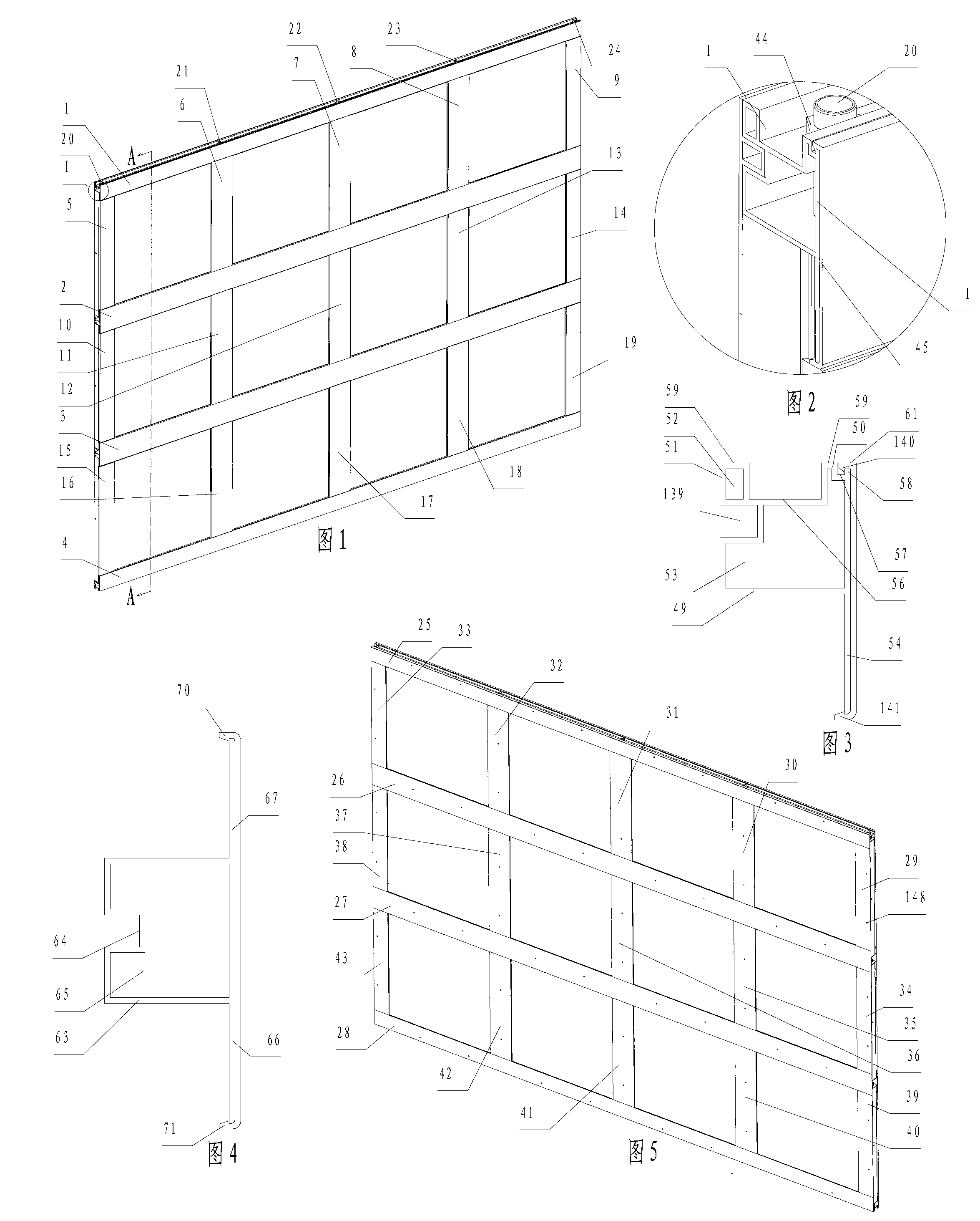
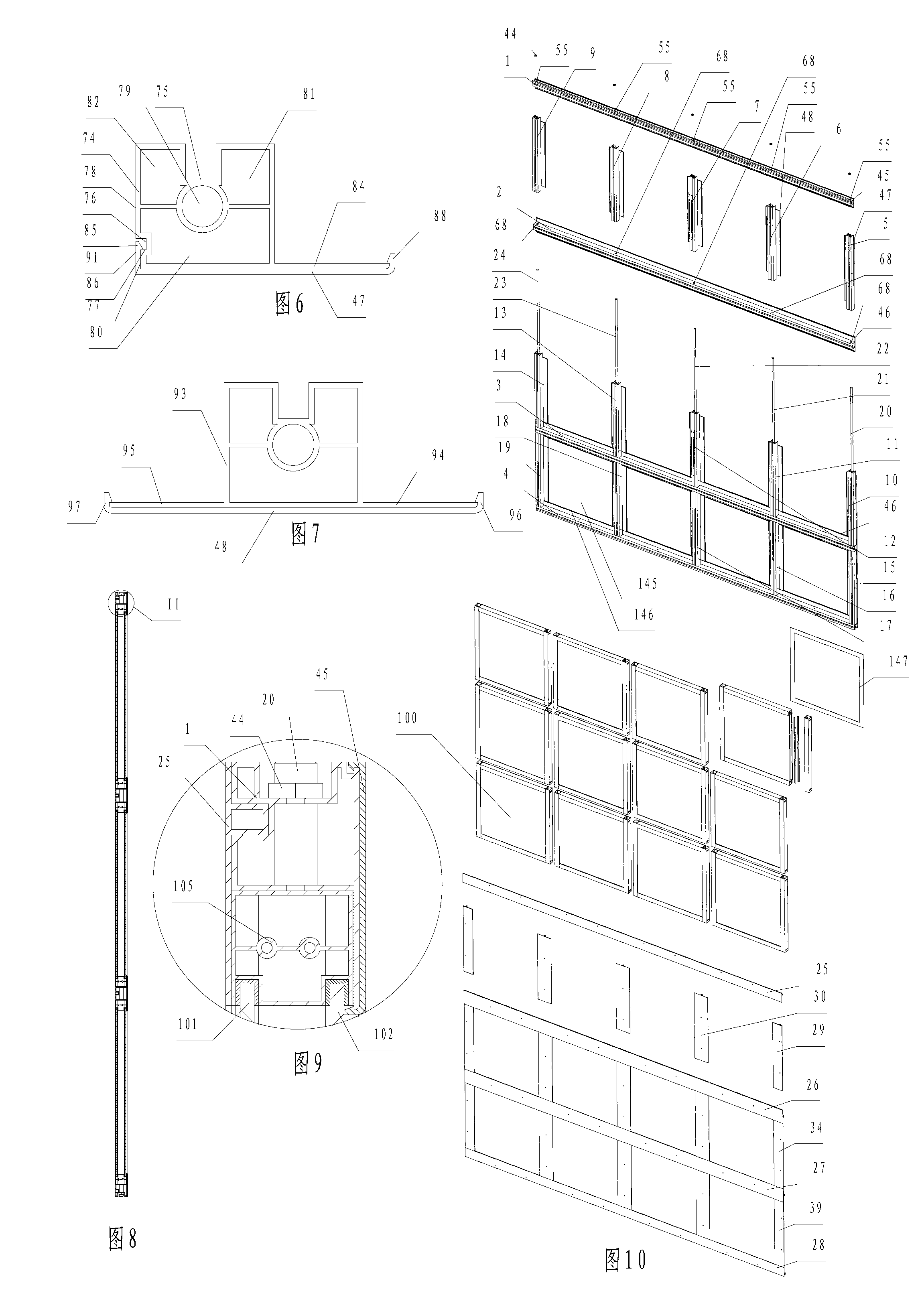
[0119] Such as figure 1 , Figure 10 As shown, a combined building structure is a combined wall structure, including the first keel 1 installed with the first outer spacer 45 in the vertical direction array from top to bottom, and the first outer spacer 46 with the same structure. And the first keel 2 and the first keel 3 with the same structure, the first keel 4 that is installed with the first outer spacer 45 with respect to the horizontal plane of the center position of the symmetry of the first keel 4, is installed on the first keel 1 and the first keel 2 Between, perpendicular to the first keel 1 and the first keel 2, the second keel 5 with the second outer spacer 47 installed vertically in the horizontal direction from left to right, the second outer spacer 48 with the same structure is installed and The second keel 6, the second keel 7 and the second keel 8 with the same structure, the second keel 9 of the second outer spacer 9 that is symmetrical with the second outer...

Embodiment 2

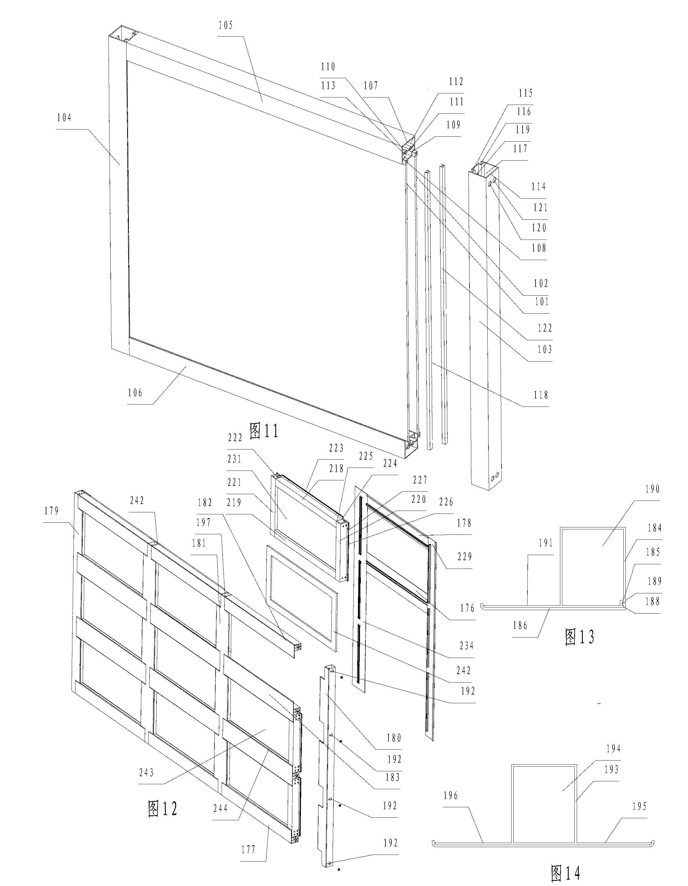
[0136] Different from Embodiment 1, there are four first keels installed vertically, and four second keels are installed horizontally between every two adjacent first keels. Such as Figure 12 , Figure 13 As shown, the rightmost first keel 180 includes a square first keel body 184, which runs through both ends of the first keel body 184 up and down, and is provided with a first card slot 185 in cooperation with the first outer spacer 186. The first keel body The right side 189 of 184 protrudes from the right side 188 of the first card slot 185 close to the groove wall on the outdoor side, and runs through the two ends of the first keel body 184 up and down, so that the wall thickness of the first keel body 184 is relatively uniform. The hole 190 is perpendicular to the left side of the first keel body 184 and protrudes from the side 191 that is flush with the surface of the first keel body 184 facing the outside. .

[0137] Such as Figure 12 , Figure 14 As shown, the f...

Embodiment 3

[0147] The difference from embodiment 2 is that all the first keel and the second keel are plastic profiles, and all the first outer spacer and the second outer spacer are metal parts.

[0148] Such as Figure 19 , Figure 20 As shown, all the first decorative strips and the second decorative strips are flat metal parts. On the side of the square first keel body 261 of the first keel 260 on the right side facing the room, a decorative raised strip 262 flush with the right side of the first keel body 261 is provided, so that the wall thickness of the first keel 260 is relatively uniform. The hollowed through hole 263 runs through the first keel body 261 and the decorative convex strip 262 . The leftmost first keel 264 is symmetrical to the rightmost first keel 260 with respect to the vertical plane at their center positions.

[0149] Such as Figure 19 , Figure 21 As shown, on the side of the square second keel body 266 facing the interior of the three second keel 265 in ...


PUM


Abstract

The invention discloses a combined construction structure which comprises first keels, second keels and an interlayer module; the adjacent two first keels and the adjacent two second keels form a square frame for installing the interlayer module; flanges which are integrated with the corresponding first keels and second keels are arranged on four inner side surfaces opposite to the square frame; elastic buckle-type profile U-shaped first external spacer bars which are laterally buckled onto the first keels, and elastic buckled-type profile U-shaped second external spacer bars which are laterally buckled onto the second keels are also arranged; one of the two buckles of the first external spacer bar of the first keel on the outermost side is buckled on the related flange, and the other is buckled in a first slot; and one of the two buckles on the second external spacer of the second keel on the outermost side is buckled on the related flange, and the other is buckled on a second slot. The combined construction structure has the advantages of good heat isolation and sound isolation effects, convenience and quickness in installation, simple process, good strength and rigidity of main keels, and low cost.

Description

technical field [0001] The invention relates to a building structure, in particular to a combined wall or combined window. Background technique [0002] In cold regions (below -30°C), in order to enhance the building's indoor thermal insulation performance, double-glazed windows are often used. Existing double glazed windows have wooden windows, plastic windows and aluminum alloy windows. Among them, in terms of performance (such as service life) and appearance, aluminum alloy windows are the most popular among users. However, the existing double-glazed aluminum alloy windows all adopt independent inner and outer two-layer window frames and two-layer sash, that is, double-frame and double-layer sash, which is not only inconvenient to install, but also has many aluminum alloy consumables, and the aluminum alloy window frame is Good thermal conductivity makes it easy to dissipate indoor heat to the outside, and at the same time, it is easy to produce frost on the surface of ...

Claims


Application Information

Patent Timeline
IPC IPC(8): E06B3/263E06B3/67E06B7/22E06B3/30E06B3/58E06B3/46E06B7/086E06B9/02E06B9/264E06B5/16E04B2/56E04B2/88E04B1/88E04B1/68
CPCE06B3/28E06B3/64E04B2/78E04B2/88E06B3/263E06B3/67E04B2/74E06B1/36E06B3/08E06B7/096
Inventor 杨东佐
Owner 深圳市华汇设计有限公司
Why Eureka
Try Eureka