
Thermal resistance composition test device and method for LED (light emitting diode) lamp

A technology of LED lamps and LED chips, which is applied in the direction of single semiconductor device testing, material thermal conductivity, etc., can solve the problems of inability to measure thermal resistance, inconvenient design and application of LED lamps, etc., and achieve the effect of expanding measurement functions

Active Publication Date: 2013-05-01
BEIJING UNIV OF TECH
View PDF6 Cites 25 Cited by
  • Summary
  • Abstract
  • Description
  • Claims
  • Application Information

AI Technical Summary

Problems solved by technology

[0003] However, in the prior art, only the thermal resistance of a single LED chip can be measured, but the thermal resistance of the assembled lamp cannot be measured. The common method is to measure the temperature at the surface of the LED lamp through the temperature measuring probe on the surface
This is extremely inconvenient for the design and application of actual LED lamps

Method used


Image

  • Thermal resistance composition test device and method for LED (light emitting diode) lamp
  • Thermal resistance composition test device and method for LED (light emitting diode) lamp
  • Thermal resistance composition test device and method for LED (light emitting diode) lamp

Examples


Embodiment Construction

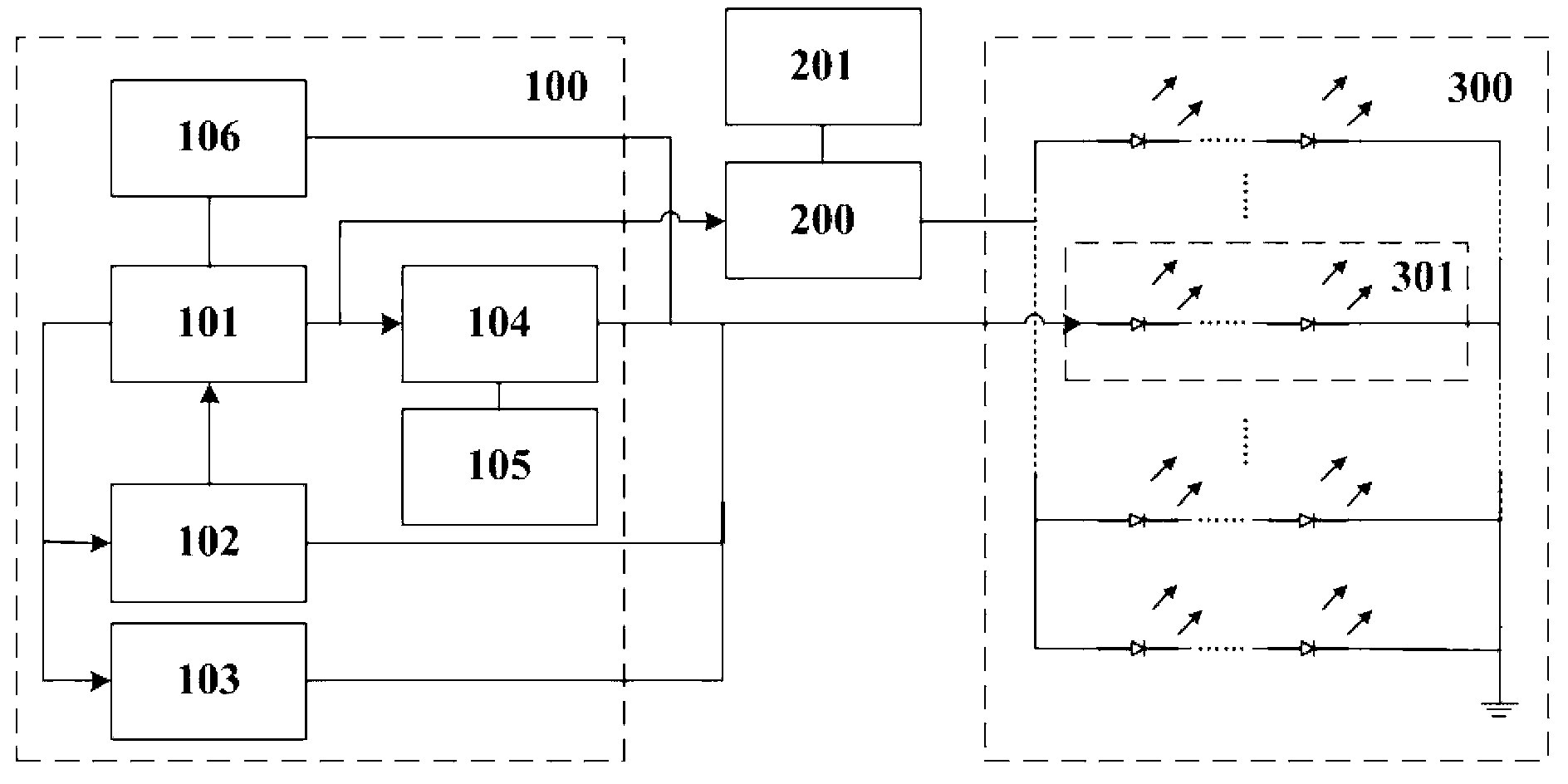
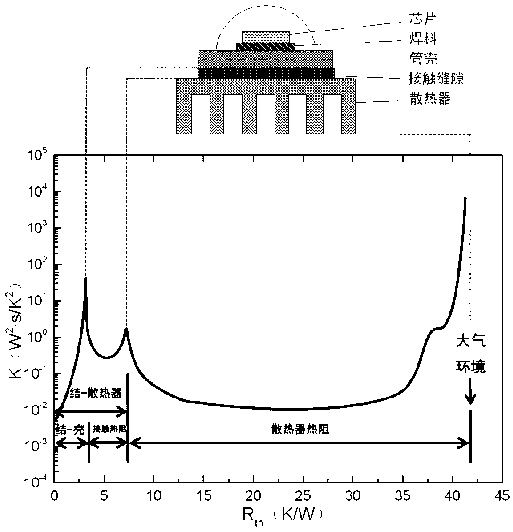
[0030] Choose the LED downlight produced by Zhuhai Shengyuan Tongtai Electronics Co., Ltd., and use this patent to test the thermal resistance of the LED chip to the heat sink. The structure of the lamp is that a plurality of high-power LED chips are connected in series and then connected in parallel. The LED chip shell is directly bonded to the surface of the radiator, and the heat dissipation method is heat conduction by a heat pipe. Before the test, first suspend and fix the tested lamp 300 in a confined space, select and separate a group of temperature measuring LED unit assemblies 301 as the temperature measuring device to be separately connected to the working power switch 104 interface of the temperature measuring LED unit assembly. The thermal resistance composition of the temperature measurement LED unit assembly 301 to the radiator is measured to achieve the purpose of obtaining the thermal resistance of the radiator, and the remaining LEDs are connected and connected ...


PUM


Abstract

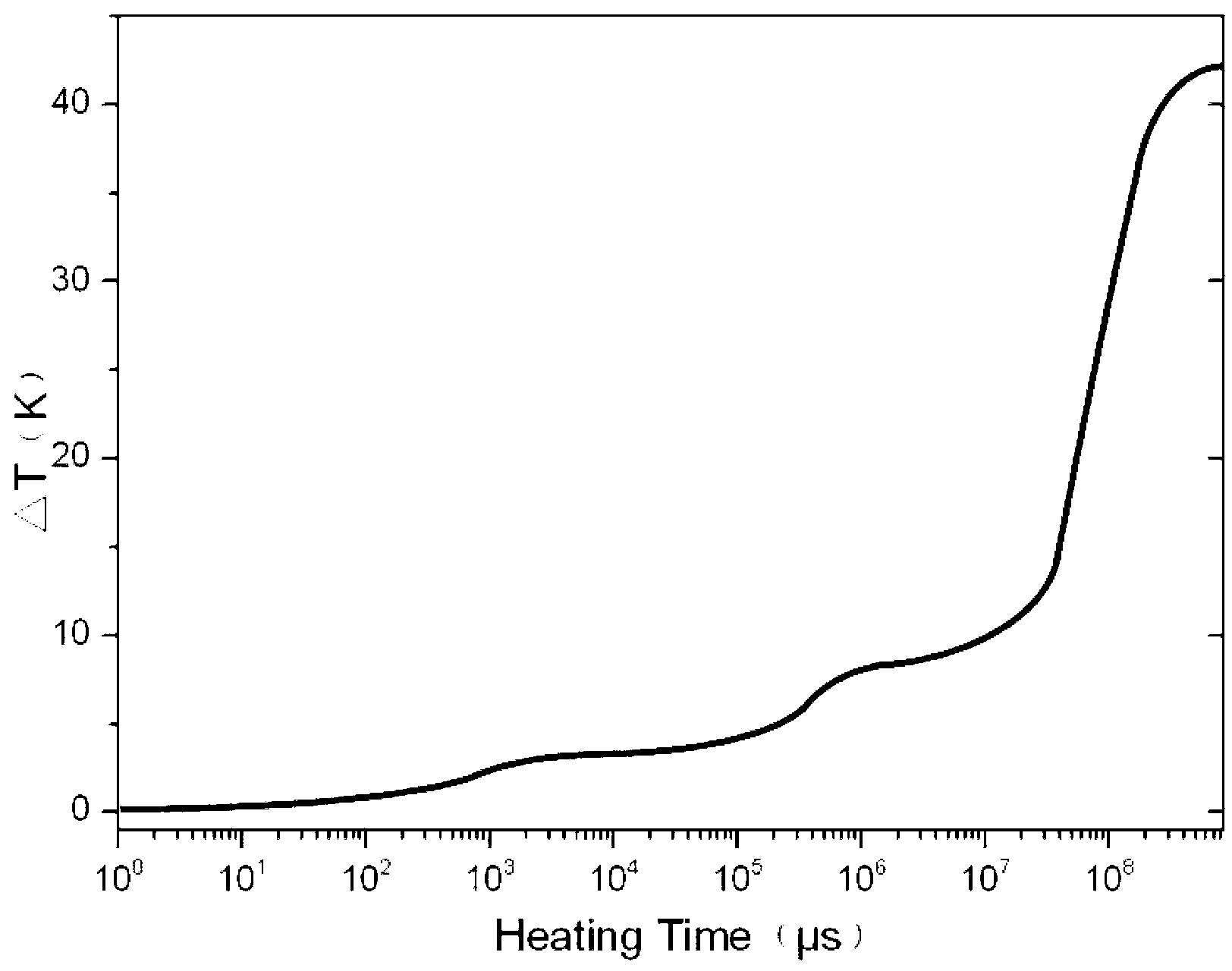
The invention relates to a thermal resistance composition test device and a thermal resistance composition method for an LED (light emitting diode) lamp, and belongs to the technical field of semiconductor LED illumination and display reliability design and checking. The device and the method provided by the invention have the main invention points that in the actual LED lamp, partial LEDs are selected and isolated to be used as temperature measuring elements, synchronous switching modes and devices for controlling an external lamp power supply are designed, the transient state temperature rise process curve collection line and methods are utilized, and the real thermal resistance composition of the LED lamp is measured on line. When the LED lamp adopts different heat radiators or the contact between the heat radiator and an LED device is poor, the heat resistance of each part is different, the heat radiation design of the LED lamp can be optimized through measuring the thermal resistance composition in different designs and equipment, the highest junction temperature of the lamp is reduced, and the service life and the quality of the LED lamp are ensured. The device and the method provided by the invention are mainly used for fast determining the thermal resistance composition of the LED lamp in a nondestructive way.

Description

Technical field: [0001] This technology belongs to the field of semiconductor LED lighting and display reliability design and assessment technology. The invention is mainly applied to a method and device for quickly and non-destructively determining the thermal resistance of LED lamps. Background technique: [0002] Semiconductor LED lighting fixtures or display panels use a certain number of power LED devices as light sources, which will generate a lot of heat during operation, which will increase the temperature at the semiconductor PN junction and reduce performance. Generally, a heat sink or an additional heat sink is used to conduct heat from the concentrated area of ​​the LED chip to the external environment to ensure that the junction temperature is lower than the safe temperature and ensure the quality of the entire lamp. [0003] However, the prior art can only measure the thermal resistance of a single LED chip, but cannot measure the thermal resistance of the lamp. The ...

Claims


Application Information

Patent Timeline
IPC IPC(8): G01R31/26G01N25/18
Inventor 冯士维史冬邓兵郭春生朱慧
Owner BEIJING UNIV OF TECH
Learn More