Method for monitoring best focal length of mask plate and exposure equipment

A technology of optimal focal length and mask plate, which is applied in the direction of microlithography exposure equipment, originals for photomechanical processing, exposure devices for photolithography, etc., can solve the problem of inaccurate response to product feature size changes, monitoring, and unfavorable Produce product feature size and other issues to achieve the effect of reducing mutual influence, high precision and improving sensitivity

Active Publication Date: 2017-08-08
SHANGHAI HUAHONG GRACE SEMICON MFG CORP
View PDF7 Cites 0 Cited by
  • Summary
  • Abstract
  • Description
  • Claims
  • Application Information

AI Technical Summary

Problems solved by technology

[0006] Although the existing part of the exposure machine has the function of monitoring the best focal length, it cannot accurately reflect the change of the characteristic size of the product produced by the exposure machine, which is not conducive to the monitoring of the characteristic size of the produced product

Method used


Image

  • Method for monitoring best focal length of mask plate and exposure equipment
  • Method for monitoring best focal length of mask plate and exposure equipment
  • Method for monitoring best focal length of mask plate and exposure equipment

Examples


Embodiment Construction

[0027] Although the existing exposure equipment can obtain the best focal length of the exposure equipment through the automatic calibration function, due to the influence of various disturbance factors such as the machine itself and the outside world during automatic calibration, the best focal length obtained is not accurate. When the best focal length exposes the photoresist layer of the product, the characteristic size of the photoresist pattern formed on the product changes, which is not conducive to the monitoring of the best focal length of the exposure machine and the characteristic size of the product.

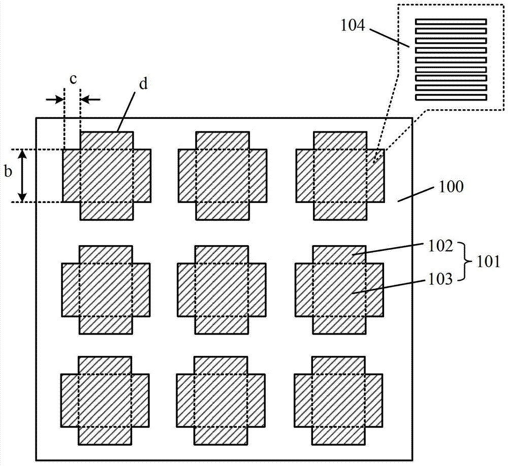
[0028] In order to solve the above problems, the embodiment of the present invention first proposes a mask, please refer to figure 1 , the mask plate 104 includes: a substrate 100 ; a monitoring pattern 101 on the substrate 100 , the monitoring pattern 101 includes a square body 103 and rectangular protrusions 102 on the side walls of the square body 103 .

[0029] Th...


PUM

PropertyMeasurementUnit
transmittivityaaaaaaaaaa

Abstract

The invention discloses a mask plate and an exposure equipment optimal-focal distance monitoring method. The mask plate comprises a base plate and a monitoring pattern on the base plate. The monitoring pattern comprises a square body and rectangular lug bosses at four sides of the square body, and the rectangular lug bosses are multiple parallel grating bars. Through the mask plate, the precision of optimal-focal distance monitoring is improved.

Description

technical field [0001] The invention relates to the field of semiconductor manufacturing, in particular to a method for monitoring the best focal length of a mask plate and exposure equipment. Background technique [0002] In the manufacturing process of semiconductor integrated circuits, the layout pattern on the mask plate is transferred to the photoresist layer of the semiconductor substrate through the exposure equipment of the photolithography process to form a photoresist pattern; then, the photoresist layer is used as a mask film layer, and perform subsequent etching or ion implantation processes on the semiconductor substrate. [0003] In the photolithography process, the feature size of the photoresist pattern and its sidewall profile will be affected by the focus of the exposure equipment. The feature size and profile of the photoresist pattern will directly affect the subsequent etching or ion implantation process. Therefore, the monitoring of the focus of the ex...

Claims


Application Information

Patent Timeline
Patent Type & Authority Patents(China)
IPC IPC(8): G03F1/44G03F7/20
Inventor 谭露璐赵新民金乐群周孟兴
Owner SHANGHAI HUAHONG GRACE SEMICON MFG CORP
Why Eureka
Try Eureka