Large-scale coal-fired boiler smoke gas flow rate soft measuring method

A flue gas flow, coal-fired boiler technology, applied in the field of boilers, can solve problems such as difficult to find front and rear straight pipe sections, corrosion measuring devices, fly ash clogging, etc., to save equipment and human resources, fast dynamic response, and accurate measurement. good effect

Inactive Publication Date: 2013-05-01
NORTH CHINA ELECTRIC POWER UNIV (BAODING)
View PDF4 Cites 21 Cited by
  • Summary
  • Abstract
  • Description
  • Claims
  • Application Information

AI Technical Summary

Problems solved by technology

[0004] At present, the measurement of flue gas flow is facing many difficulties
First of all, the cross-section of the flue gas flow channel of a large boiler is rectangular and very thick, and there are various heating surfaces and other equipment arranged in the flue, it is difficult to find a suitable position for installing the flow measurement device, and the front and rear straight pipe sections cannot meet the requirements; secondly, the flue gas carries There are a large number of fly ash particles, which will cause serious wear and tear to the conventional measuring device when flowing at high speed. At the same time, the fly ash will also deposit in the pressure pipe of the measuring device and cause blockage, which makes it difficult to guarantee the service life of the measuring device; Also contains SO 2 , NO X After the temperature drops to a certain level, these gases will chemically react with the water vapor in the flue gas to form a corrosive liquid, which will corrode the measuring device and bond the smoke and dust, resulting in a decrease in the accuracy of the measuring device or damage, especially if there is an air leakage point in the flue. This phenomenon is more likely to happen; finally, because the flue gas flow measurement device is a non-standard throttling device, its flow coefficient needs to be calibrated on site, and the calibration environment is very harsh. It is difficult to install and remove the standard measurement device, resulting in high calibration costs. , and can only be calibrated in a cold state, the calibration accuracy is difficult to guarantee

Method used


Image

  • Large-scale coal-fired boiler smoke gas flow rate soft measuring method

Examples


Embodiment Construction

[0031] The present invention carries out according to the following steps:

[0032] (1) Flue gas flow calculation

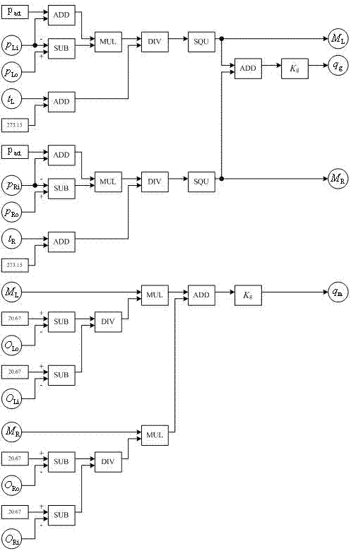
[0033] The formula for calculating the flue gas flow at the outlet of the induced draft fan is:

[0034] (1)

[0035] in: q g is the flue gas flow rate at the outlet of the induced draft fan (Nm 3 / s); K g is the discharge coefficient (dimensionless); M L is the flue gas flow variable in the p.u. left flue (Nm 3 / s); M R is the flue gas flow variable in the p.u. right flue (Nm 3 / s).

[0036] The formula for calculating the flue gas flow at the outlet of the economizer is:

[0037] (2)

[0038] in: q m is the flue gas flow rate at the outlet of the economizer (Nm 3 / s); O Li Oxygen content of the flue gas before the left air preheater (%); O Lo Oxygen content of the flue gas after the left air preheater (%); O Ri Oxygen content of the flue gas before the air preheater on the right side (%); O Ro It is the flue gas oxygen conten...


PUM


Abstract

The invention relates to a large-scale coal-fired boiler smoke gas flow rate soft measuring method. The method is used for measuring the left side draft fan inlet smoke gas pressure pLi(kPa) of a large-scale coal-fired boiler, the left side draft fan outlet smoke gas pressure pLo (kPa) of the large-scale coal-fired boiler, the local atmospheric pressure pact (kPa), the left side draft fan inlet smoke gas temperature tL (DEG C), the right side draft fin inlet smoke gas pressure pRi (kPa), the right side draft fan outlet smoke gas pressure pRo (kPa) and the right side draft fan inlet smoke gas temperature tR (DEG C) in real time, and in addition, the draft fan outlet smoke gas flow rate qg is calculated according to the flow rate-pressure characteristics of the draft fan. Compared with the traditional coal-fired boiler smoke gas flow rate measuring method, the method provided by the invention has the advantages that the reliability is high, the measurement accuracy is good, the dynamic response speed is high, the implementation cost is low, the maintenance is simple, and the like.

Description

technical field [0001] The invention relates to a method for measuring flue gas flow of a large coal-fired boiler, belonging to the technical field of boilers. Background technique [0002] Fuel chemically reacts with oxygen in the air in the boiler to generate flue gas and release heat. Accurate measurement of flue gas flow will help to implement more effective monitoring and control of the combustion process and related equipment, and optimize the entire combustion process of wind and coal. The dynamic and accurate proportioning in the boiler improves the combustion efficiency of the boiler. [0003] In addition, in order to effectively control the emission of air pollutants, large-scale boilers in thermal power plants have generally installed desulfurization equipment, and have begun to gradually install denitrification equipment. In the process of desulfurization and denitrification, in addition to the need for real-time and accurate measurement of SO in flue gas 2 , N...

Claims


Application Information

Patent Timeline
Patent Type & Authority Applications(China)
IPC IPC(8): G06F19/00
Inventor 田亮刘鑫屏霍秋宝武现聪
Owner NORTH CHINA ELECTRIC POWER UNIV (BAODING)
Why Eureka
Try Eureka