Electrically heated catalyst
An electric heating type, catalyst technology, applied in the direction of machine/engine, mechanical equipment, engine components, etc., can solve the problem of EHC exhaust gas purification ability reduction and other problems, and achieve the effect of suppressing short circuit
- Summary
- Abstract
- Description
- Claims
- Application Information
AI Technical Summary
Problems solved by technology
Method used
Image
Examples
Embodiment 1
[0034] [Outline structure of EHC]
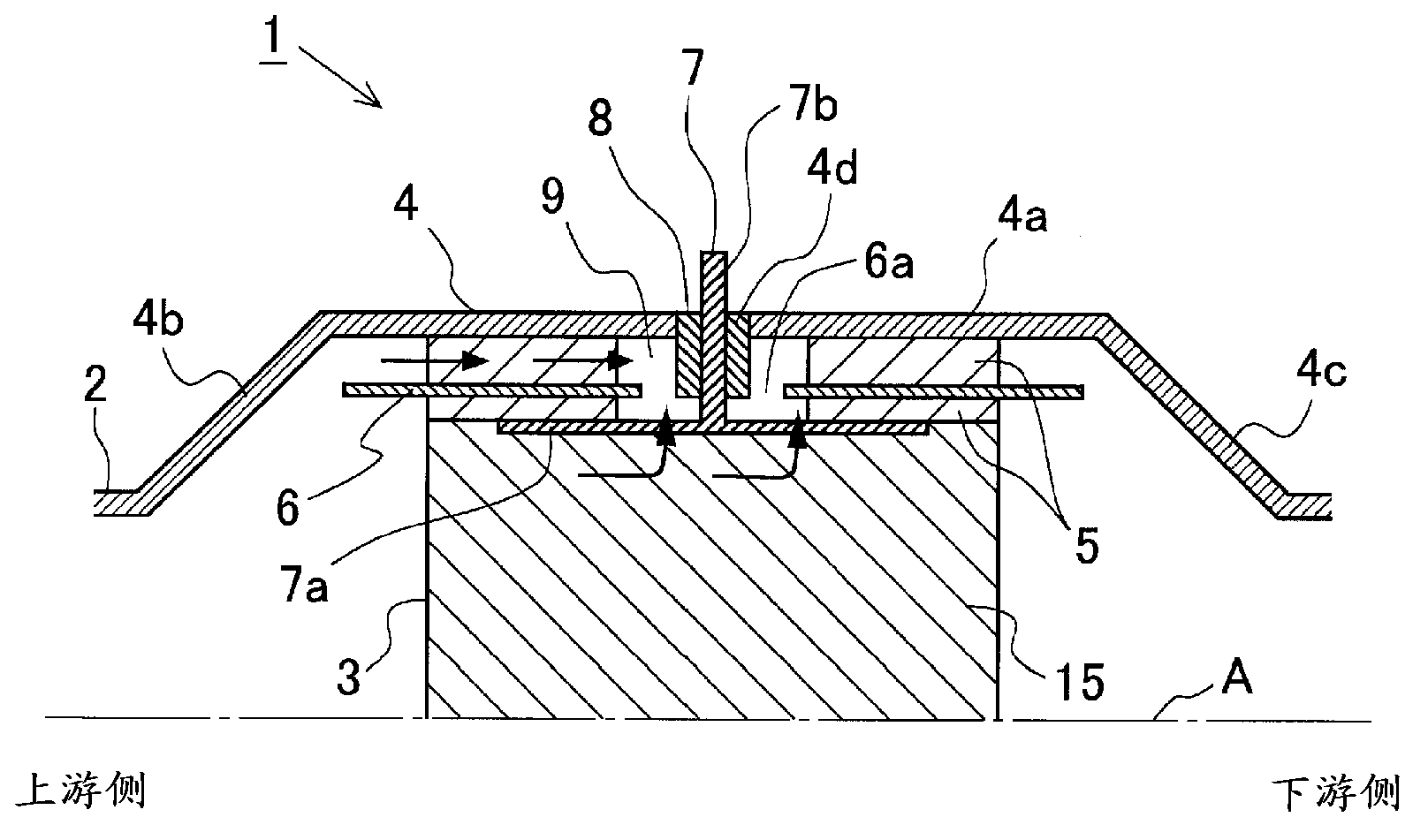
[0035] figure 1 It is a diagram showing a schematic configuration of an electrically heated catalyst (EHC) according to the present example. The EHC 1 according to this embodiment is installed in an exhaust pipe of an internal combustion engine mounted on a vehicle. The internal combustion engine can be a diesel engine or a gasoline engine. Furthermore, the EHC 1 according to the present embodiment can also be used in a vehicle using a hybrid system including an electric motor.
[0036] figure 1 It is a cross-sectional view of the EHC 1 cut along the central axis A of the exhaust pipe 2 of the internal combustion engine in the longitudinal direction. In addition, since the shape of EHC1 is line-symmetric with respect to the central axis A, in figure 1 In FIG. 2 , only the upper side of EHC1 is shown for convenience.
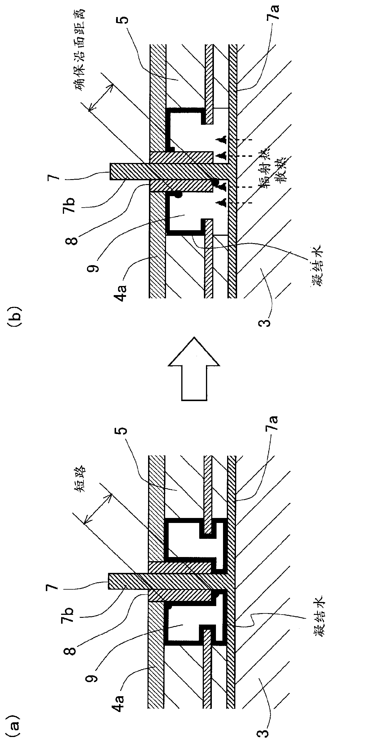
[0037] The EHC 1 according to this example includes a catalyst carrier 3 , a case 4 , a gasket 5 , an inner tube 6 , an...
Embodiment 2
[0058] [Outline structure of EHC]
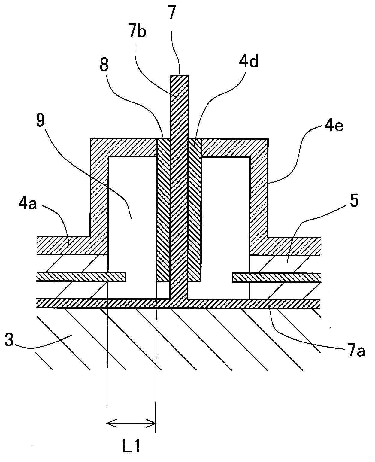
[0059] image 3 It is an enlarged view of a portion forming the electrode chamber of the EHC according to the present example. Such as image 3 As shown, in this embodiment, the portion 4e that forms the wall surface of the electrode chamber 9 and the portion 4e that forms the through hole 4d through which the shaft portion 7b of the electrode 7 passes in the housing portion 4a of the housing 4 is formed as compared to The other part of the accommodating part 4a of the housing 4 has a convex shape protruding outward (hereinafter, this part is referred to as a convex shape part).
[0060] In the present embodiment, as in the first embodiment, the support member 8 extends from the through-hole 4 d of the case 4 to a position capable of receiving radiant heat and radiated heat from the catalyst carrier 3 . In addition, the convex shape part 4e is formed so that the distance L1 between the inner side wall surface of the convex shape part 4e a...
Embodiment 3
[0068] [Outline structure of EHC]
[0069] Figure 5 It is an enlarged view of a portion forming the electrode chamber of the EHC according to the present example. Such as Figure 5 As shown, in this embodiment, the part of the supporting member 8 that protrudes into the electrode chamber 9 has a cone in which the cross-sectional area in the direction perpendicular to the axial direction of the shaft portion 7b of the electrode 7 becomes smaller as it goes toward the front end. shape. That is, the cross-sectional area of the support member 8 in a direction perpendicular to the axial direction of the shaft portion 7b of the electrode 7 is smaller at the portion close to the catalyst carrier 3 than the portion close to the inner wall surface of the case 4. . Other configurations are the same as those of the EHC according to Example 1.
[0070] [Action and effect of the structure of the EHC according to the present embodiment]
[0071] According to the present embodiment,...
PUM
 Abstract
Description
Claims
Application Information
 - R&D
- Intellectual Property
- Life Sciences
- Materials
- Tech Scout
- Unparalleled Data Quality
- Higher Quality Content
- 60% Fewer Hallucinations
Browse by: Latest US Patents, China's latest patents, Technical Efficacy Thesaurus, Application Domain, Technology Topic, Popular Technical Reports.
© 2025 PatSnap. All rights reserved.Legal|Privacy policy|Modern Slavery Act Transparency Statement|Sitemap|About US| Contact US: help@patsnap.com


