Method for adjusting the rotor position of an electrically commutated motor

A technology of rotor position and rotor, which is applied in the direction of electronically commutated motor control, electronic commutator, monitoring commutation, etc., can solve the problem of discontinuous and strong amplitude torque change, and achieve the effect of reducing computing power

Inactive Publication Date: 2013-05-01
SCHAEFFLER TECH AG & CO KG
View PDF4 Cites 2 Cited by
  • Summary
  • Abstract
  • Description
  • Claims
  • Application Information

AI Technical Summary

Problems solved by technology

Furthermore, the disadvantage of locked commutations is that th

Method used


Image

  • Method for adjusting the rotor position of an electrically commutated motor
  • Method for adjusting the rotor position of an electrically commutated motor
  • Method for adjusting the rotor position of an electrically commutated motor

Examples


Example Embodiment

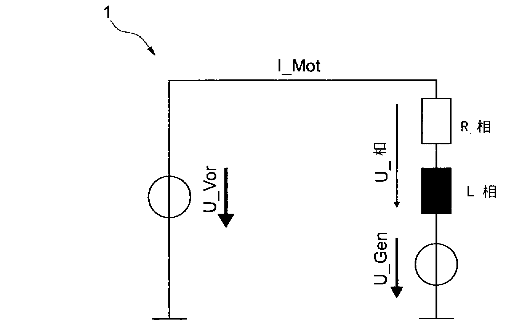
[0023] figure 1 An alternative circuit diagram for one phase of an electrically commutated motor 1 is shown, which is configured as a brushless direct current motor (BLDC motor). Such electric motors are used, for example, to control clutches in motor vehicles. This is an AC motor, which runs on alternating current, which is caused by three alternating voltages with a phase shift of 120° and generates a rotating field. The motor has three AC coils, wherein one of the three AC voltages is applied to each coil. The joints of the coils are referred to herein as phases. Here, each coil is an impedance, which is characterized by L phase (inductive reactance) and R phase (reeller widerstand).

[0024] In the case of high speed, the motor current I-Mot lags behind the motor voltage U-Gen due to the motor inductance L-phase. In order to determine the position of the motor rotor with an accuracy of at least 1 degree, the motor current I-Mot must be accurately adapted to the rotor posit...


PUM


Abstract

The invention relates to a method for adjusting a rotor position of an electrically commutated motor, in particular a brushless DC motor, in which the phases of the motor are actuated after determination of the rotor position via a block commutation. The invention is characterized in that the actuation of the motor phases is switched from block commutation to time-controlled commutation in order to adjust the rotor position with high precision.

Description

technical field [0001] The invention relates to a method for adjusting the rotor position of an electrically commutated motor, in particular a brushless DC motor, in which method, after the rotor position has been determined, the phases of the motor are controlled by event-controlled commutation. Background technique [0002] "Event-controlled" in the sense of the present invention means that an event is detected (for example a Hall interruption or a defined angle) and commutation takes place on the basis of the detected event (preferably via the control software). An example of event-controlled commutation is "deadlock commutation". [0003] Electrically commutated motors such as those employed in clutch actuators need to be able to adjust the rotor position of the motor with high resolution. A vector adjustment can be performed for this. The vector control or field-oriented control can include a rotational speed control based on an underlying current control. In this ca...

Claims


Application Information

Patent Timeline
IPC IPC(8): H02P6/14H02P6/12
CPCH02P6/12H02P6/142H02P6/15
Inventor M·拉普C·昂里克M·齐默尔曼
Owner SCHAEFFLER TECH AG & CO KG
Why Eureka
Try Eureka