Infrared imaging non-uniformity intelligent calibration and correction method and system

A non-uniformity correction and non-uniformity technology, which is applied in the field of infrared imaging non-uniformity intelligent calibration and correction, and achieves the effects of less number, less memory, and low time and space complexity.

Inactive Publication Date: 2021-08-17
BEIJING INFORMATION SCI & TECH UNIV
View PDF3 Cites 2 Cited by
  • Summary
  • Abstract
  • Description
  • Claims
  • Application Information

AI Technical Summary

Problems solved by technology

The invention solves the problem that the calibration-based non-uniformity correction method needs to periodically reset the parameters of the infrared detector passively, and can greatly reduce the probability of accidents caused by the interruption of image acquisition and untimely detection of infrared detection equipment in industrial applications

Method used


Image

  • Infrared imaging non-uniformity intelligent calibration and correction method and system
  • Infrared imaging non-uniformity intelligent calibration and correction method and system
  • Infrared imaging non-uniformity intelligent calibration and correction method and system

Examples


Embodiment 1

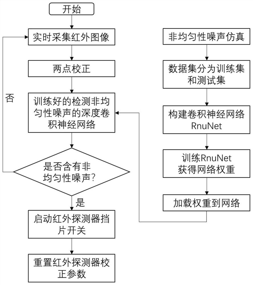
[0054] An intelligent calibration and correction method for infrared imaging non-uniformity, such as figure 1 shown, including the following:

[0055] S1: Perform two-point correction on the currently collected infrared original image to remove multiplicative and additive non-uniformity noise;

[0056] Further, the two-point correction calculation formula is as follows:

[0057] Y ij (n)=K ij (n).X ij (n)+B ij (n)

[0058] Among them, Y ij (n) is the corrected gray value of the two points at the detector pixel (i, j) of the nth frame; X ij (n) is the response value of the detector pixel (i, j) in the nth frame; K ij (n) is the gain correction value of the detector pixel (i, j) in the nth frame; B ij (n) is the offset correction value of the detector pixel (i, j) in the nth frame;

[0059] Gain and offset correction values ​​can be expressed as:

[0060]

[0061]

[0062] Among them, T H and T L Indicates high and low temperature points; with Respectively...

Embodiment 2

[0084] A calibration-based intelligent infrared imaging non-uniformity correction system, such as Figure 4 As shown, it includes an infrared optical system, an infrared detector and a radiation shield, and also includes an infrared image processing system. The infrared image processing system includes a non-uniformity correction unit, a non-uniformity neural network detection unit, a radiation shield control unit, and an infrared detection The device obtains the infrared radiation analog signal of the target scene in real time through the infrared optical system, and transmits it to the infrared image processing system after analog-to-digital conversion. The infrared image processing system first performs two-point correction on the input infrared radiation digital signal through the non-uniformity correction unit. , and then sent to the non-uniform neural network detection unit to detect whether the two-point corrected image contains non-uniform noise, if it contains non-unif...

Embodiment 3

[0099] In the detection non-uniformity noise convolutional neural network RnuNet among the present invention, the network structure is specifically described as follows:

[0100] The RnuNet of the present invention is composed of 5 convolutional layers, 2 fully connected layers and 1 output layer. The five convolutional layers are respectively denoted as C1, C2, C3, C4 and C5; the two fully connected layers are denoted as FC6 and FC7 respectively.

[0101] The input image size is 227x227. The 5 convolution layers use convolution kernels with sizes of 11x11, 5×5 and 3×3 for convolution operations, among which the C1 layer uses 11x11 convolution kernels, and the C2 layer uses 5×5 convolution Kernel, layers C3 to C5 use 3×3 convolution kernels. The number of convolution kernels C1-C5 layers are 96, 256, 256, 256 and 128 respectively. The five convolution layers respectively input the feature maps obtained after convolution to the ReLU function for activation. The C1 layer, C2 l...


PUM


Abstract

The invention relates to an infrared imaging non-uniformity intelligent calibration and correction method and system, and belongs to the technical field of infrared imaging systems. The method comprises the following steps: firstly, carrying out two-point correction on a currently collected infrared original image; inputting the corrected image into a trained deep convolutional neural network for non-uniformity noise detection; and if the detection result is that the non-uniform noise is contained, starting a baffle switch of the infrared detector, and resetting correction parameters of the infrared detector. Compared with the prior art, the method has the advantages that the deep convolutional neural network is used for intelligently detecting the non-uniformity noise, and the problem that a radiation blocking piece in an infrared imaging system needs to be periodically and passively operated and parameters of an infrared detector need to be reset in an existing calibration-based non-uniformity correction method is solved; therefore, the operation frequency of the radiation separation blade of the existing infrared imaging system is greatly reduced, and the probability of accidents caused by interruption of image acquisition and untimely detection is reduced.

Description

technical field [0001] The invention relates to the technical field of infrared imaging systems, in particular to a method and system for intelligent calibration and correction of infrared imaging non-uniformity. Background technique [0002] The problem of non-uniformity is limited by the manufacturing process of infrared imaging devices, which leads to a decrease in the detection capability of the infrared imaging system, which is reflected in the fixed pattern noise in the infrared image, which seriously affects the quality of the infrared image. Currently, there are two types of non-uniformity correction methods, which are calibration-based correction methods and scene-based correction methods. The scene-based correction method needs sufficient movement of the scene, otherwise problems such as ghosting will appear, and the time and space complexity of the algorithm is high, which is not conducive to embedded implementation. The calibration-based correction method has th...

Claims


Application Information

Patent Timeline
Patent Type & Authority Applications(China)
IPC IPC(8): G01J5/00G06T5/00G06N3/04
CPCG01J5/00G06T5/006G06T5/002G01J2005/0077G06T2207/20081G06T2207/20084G06T2207/10048G01J5/48G01J5/80G06N3/045
Inventor 邓峰刘军姚振
Owner BEIJING INFORMATION SCI & TECH UNIV
Why Eureka
Try Eureka