Method and special rack capable of adjusting position of suspended beam screw rod to guide rail

A hanging beam screw and special-purpose technology, which is applied to measuring devices, mechanical measuring devices, and mechanical devices, etc., can solve the problems of being difficult to master, labor-consuming and time-consuming, and complicated to operate. simple effect

Inactive Publication Date: 2013-05-08
SUZHOU LEAD LASER TECH +2
View PDF7 Cites 14 Cited by
  • Summary
  • Abstract
  • Description
  • Claims
  • Application Information

AI Technical Summary

Problems solved by technology

This method is cumbersome and requires the operator to have a high level of technical theory. It is labor-intensive, time-consuming, complicated to operate, and difficult to master.

Method used


Image

  • Method and special rack capable of adjusting position of suspended beam screw rod to guide rail
  • Method and special rack capable of adjusting position of suspended beam screw rod to guide rail
  • Method and special rack capable of adjusting position of suspended beam screw rod to guide rail

Examples


Embodiment Construction

[0022] The present invention will be described in detail below in conjunction with accompanying drawing and specific embodiment

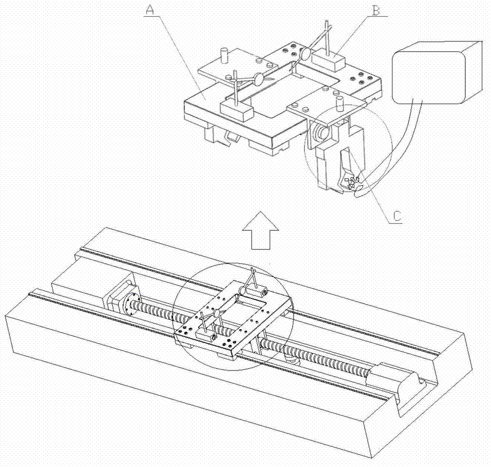
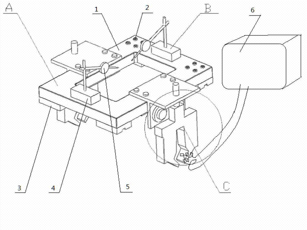
[0023] Such as Figure 1-3 As shown, the present invention provides a special frame for adjusting the position of the hanging beam screw to the guide rail. The special frame includes a frame A, a detection device B and a clamping device C. The frame A includes a return-shaped plate 1 and a guide rail slider 3 , one end of the return-form plate 1 is connected to the guide rail slider 3 through a first screw 2 , and the other end is in natural contact with the guide rail slider 3 .

[0024] The detection device B includes two sets of micrometers 5, which are respectively located on both sides of the frame A. The both sides of back-shaped plate 1 being in guide rail position are adsorbed and equipped with magnetic gauge base 4 respectively, and micrometer 5 is fixed on the frame A by magnetic gauge base 4, and dial gauge 5 measuring positions, height ...


PUM


Abstract

The invention provides a method capable of adjusting the position of a suspended beam screw rod to a guide rail. The method includes the steps of aligning a special rack on the guide rail screw rod with the known accuracy, reading data on a data acquisition unit and zero clearing, arranging the adjustment rack on the parallel guide rail to be detected, clamping screw rod nut through a clamping device, contacting the screw rod nut with a pressure sensor, and displaying a pressure value of a contact point of a clamping device mechanical arm and the screw rod in real time by being connected with the data acquisition unit. The special rack is capable of slowly moving on the guide rail through rotation of the screw rod to achieve automatic detection. A dial indicator which is arranged on the special rack is capable of being used for detecting, when the screw rod is arranged or positional accuracy of the screw rod is periodically detected. The method capable of adjusting the position of the suspended beam screw rod to the guide rail has the advantages of being simple in structure, reasonable in design, high in installation accuracy, capable of automatically detecting, integral in installation and detection, easy to operate and convenient to handle. The invention further provides the special rack capable of adjusting the position of the suspended beam screw rod to the guide rail.

Description

technical field [0001] The invention relates to the field of laser cutting machine manufacturing, in particular to a method for adjusting the position of a hanging beam screw to a guide rail and a special frame. Background technique [0002] The adjustment method of the hanging beam lead screw of the existing laser cutting machine is to place the finished angle iron buckle on the guide rail surface of the machine tool, the magnetic base of the dial indicator is adsorbed on the angle iron, and first point the side head of the dial indicator to On the upper busbar of the lead screw, push the angle iron to drive the dial indicator to move along the direction of the guide rail, and record the runout value and the direction away from the center of each section of the lead screw; The iron drives the dial indicator to move along the direction of the guide rail, and records the beating value of each section of the screw and the direction of the offset center. Analyze the distance a...

Claims


Application Information

Patent Timeline
Patent Type & Authority Applications(China)
IPC IPC(8): B23P19/00G01B5/00
Inventor 冯爱新郭儒成薛伟王瑞延顾永玉
Owner SUZHOU LEAD LASER TECH
Why Eureka
Try Eureka