
Screw automatic assembly machine

An assembly machine and automatic technology, which is applied in the direction of assembly machines, metal processing equipment, manufacturing tools, etc., can solve the problems that the assembly mechanism cannot realize automatic work, the qualified rate of finished products is not high, and the production efficiency is not high, so as to save operating manpower and Human resources, high production stability, and the effect of improving the production pass rate

Active Publication Date: 2013-05-08
南宁燎旺车灯股份有限公司
View PDF5 Cites 8 Cited by
  • Summary
  • Abstract
  • Description
  • Claims
  • Application Information

AI Technical Summary

Problems solved by technology

At present, the assembly equipment on the market is a semi-automatic assembly machine. Its structure is a combination of feeding mechanism, assembly mechanism and discharging mechanism. It has certain defects. For example, the assembly mechanism cannot realize fully automatic work and needs to be assembled by manual operation of the assembly mechanism , at the same time, the stability of the traditional equipment combination is not high, resulting in low production efficiency, low pass rate of finished products, and low intelligence. At the same time, at least one employee needs to be arranged to operate

Method used


Image

  • Screw automatic assembly machine
  • Screw automatic assembly machine

Examples


Embodiment Construction

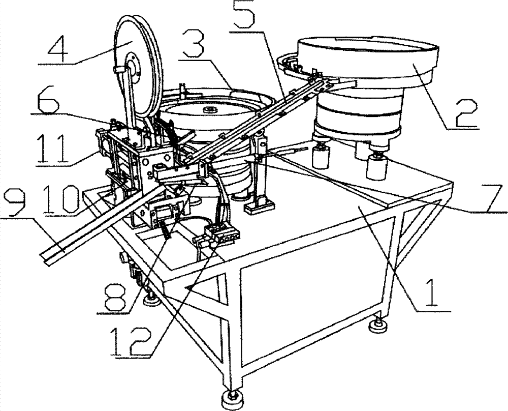
[0018] In order to make the object, technical solution and advantages of the present invention clearer, the present invention will be further described in detail below in conjunction with the accompanying drawings and embodiments. It should be understood that the specific embodiments described here are only used to explain the present invention, not to limit the present invention.

[0019] The present invention will be further described in detail below in conjunction with the accompanying drawings and specific embodiments.

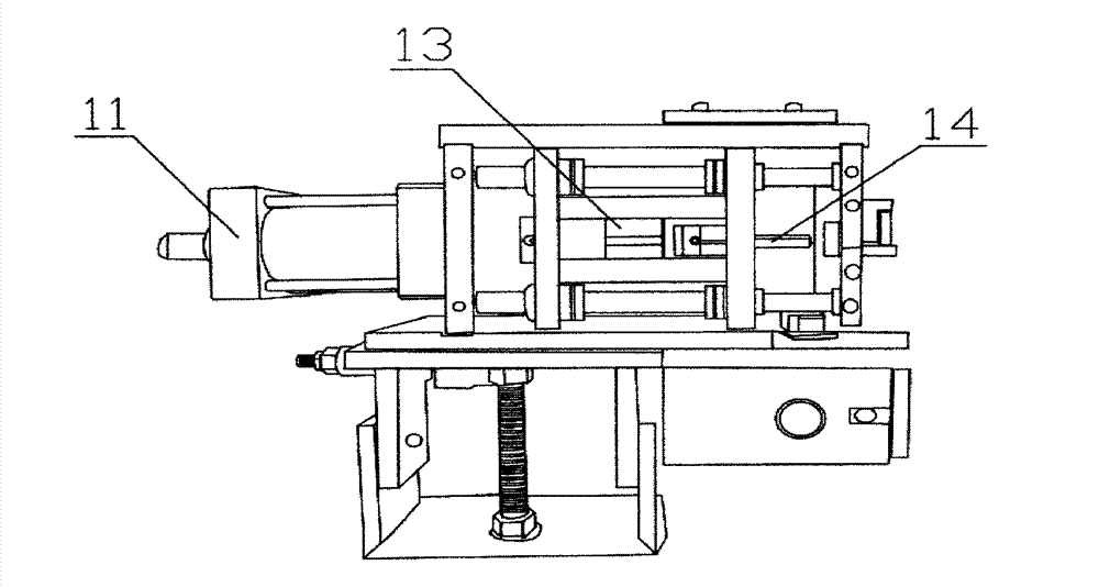
[0020] In this embodiment, refer to figure 1 and figure 2 , an automatic screw assembly machine, including a fixed base 1 and a control electric box (not shown), the control electric box and the fixed base 1 are split structures, and can be directly connected and used during use. On the top plane of the fixed base 1, there are vibrating feeding tray 1 2 for conveying metal cylinders and vibrating feeding tray 2 3 for conveying tapered wedges. The vibrat...


PUM


Abstract

The invention discloses a screw automatic assembly machine and belongs to the field of mechanical equipment for machining and assembling. The screw automatic assembly machine comprises a fixed base and a control electricity box. A first vibration feed plate and a second vibration feed plate are arranged on the top end surface of the fixed base, wherein the first vibration feed plate is used for transporting a metal cylinder and the second vibration feed plate is used for transporting a cone-shaped wedge. A punching assembly mechanism is further arranged on the top of the fixed base. A roll material fixed plate is arranged on the top of the punching assembly mechanism and used for transporting roll materials. The punching assembly mechanism is composed of a punching cylinder and a stamping assembly cylinder. A movable rod of the punching cylinder is provided with a cylindrical punching rod. The punching cylinder is arranged on a movable rod of the stamping assembly cylinder. The stamping assembly cylinder moves to drive the simultaneous movement of the punching rod. The screw automatic assembly machine has the advantages of being capable of achieving intelligent productive process of automatic feeding and automatic material collection, high in stability of production, and capable of saving operation staff and human resources, improving working efficiency and simultaneously guaranteeing safe production.

Description

technical field [0001] The invention relates to the field of mechanical equipment used for processing and assembly, in particular to an automatic assembly machine. Background technique [0002] The fixing of the expansion screw is to use the wedge-shaped inclination to promote the expansion to generate friction and grip force to achieve the fixing effect. It is generally used for the fastening of guardrails, awnings, air conditioners, etc. on cement, bricks and other materials. Making expansion screws is to assemble the parts together to form a complete product, that is, to press the tapered wedge into the metal cylinder. At present, the assembly equipment on the market is a semi-automatic assembly machine. Its structure is a combination of feeding mechanism, assembly mechanism and discharging mechanism. It has certain defects. For example, the assembly mechanism cannot realize fully automatic work and needs to be assembled by manual operation of the assembly mechanism , At...

Claims


Application Information

Patent Timeline
Patent Type & Authority Applications(China)
IPC IPC(8): B23P21/00
Inventor 邓建国旷林昌玉进
Owner 南宁燎旺车灯股份有限公司
Learn More