

Valve base compression mould of chlorine gas valve
A technology of compression mold and valve seat, which is applied in the field of valve seat compression mold, which can solve the problems of weak connection, easy leakage, falling off, etc., and achieve the effects of uniform force, enhanced sealing performance, and reliable positioning
- Summary
- Abstract
- Description
- Claims
- Application Information
AI Technical Summary
Problems solved by technology
Method used
Image

Examples
Embodiment Construction
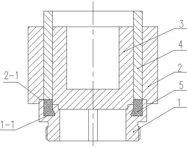
[0008] Such as figure 1 As shown, the present invention includes a valve seat base 1, an annular outer mold 2, and a step 2-1 is set at the lower end of the annular outer mold 2; the valve seat base 1 is arranged below the valve seat base 1 through the step 2-1; Inside the outer mold 2, a positioning mold core 3 is set above the valve seat base 1, and the lower end of the positioning mold core 3 and the upper end of the valve seat base 1 are arranged through a joint; between the positioning mold core 3 and the annular outer mold 2, it can be slidably arranged Forced molded sleeve 4; on the valve seat base 1 corresponding to the lower end of the stressed molded sleeve 4, an annular groove 1-1 with the same width as the thickness of the stressed molded sleeve 4 is set, and the notch of the annular groove 1-1 The width is smaller than the width of the bottom of the groove; the molded material 5 is set between the lower end of the stressed molded sleeve 4 and the annular groove 1-...
PUM
 Abstract
Description
Claims
Application Information