Lamination device

A lamination device and lamination film technology, applied in the direction of lamination device, lamination, lamination control, etc., can solve the problems of inspection abnormality, heating operation out of control, etc., to prevent misoperation, accelerate the rising speed, and suppress the influence Effect

Inactive Publication Date: 2016-03-16
SAKAE CO LTD
View PDF3 Cites 0 Cited by
  • Summary
  • Abstract
  • Description
  • Claims
  • Application Information

AI Technical Summary

Problems solved by technology

[0008] In addition, even in Patent Document 2, since a far-infrared tube heater is used as a heating unit, for example, a temperature control system (temperature detector, temperature control device) is indispensable not only for the heating unit, but also by heating The heating operation performed by the unit may be out of control when it is abnormal, and abnormal countermeasures must be taken to check the abnormality

Method used


Image

  • Lamination device
  • Lamination device
  • Lamination device

Examples


Embodiment approach 1

[0094] — Lamination device —

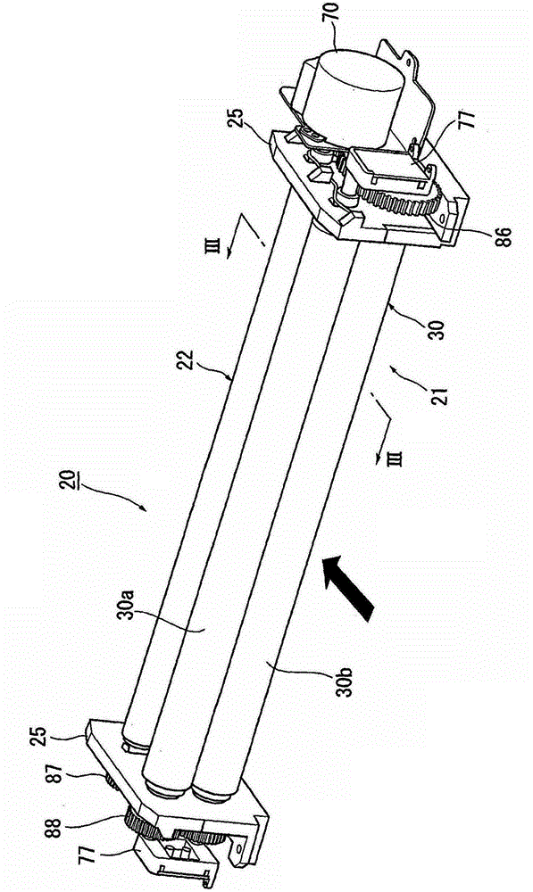
[0095] figure 2 as well as image 3 Embodiment 1 of the laminator to which the present invention is applied is shown.

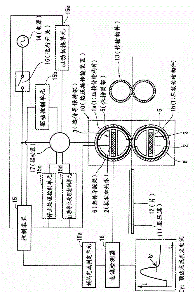
[0096] In this figure, the laminator 20 includes a thermocompression bonding transfer device 21 that is thermocompression-bonded while conveying a lamination film 101 and a sheet 102 in a superimposed manner, and is disposed on the downstream side of the thermocompression bonding transfer device 21 in the sheet transfer direction. The paired transport rollers 22 on the top are supported by the supporting side plates 25 of the housing.

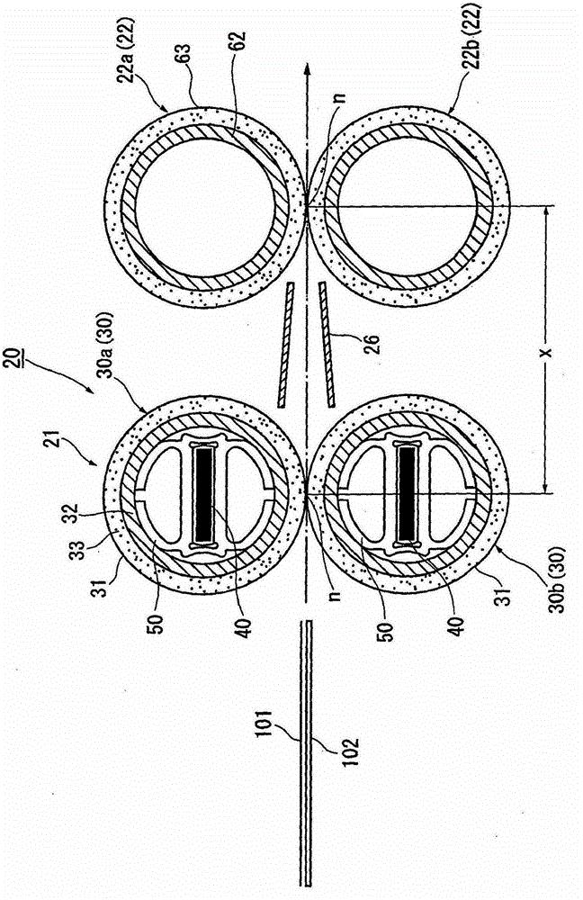
[0097] In the present embodiment, the thermocompression bonding transfer device 21 is constituted by a pair of thermocompression bonding transfer rollers 30 (specifically, 30a, 30b).

[0098] The pair of thermocompression transfer rollers 30 includes: a pair of crimp transfer rollers 31 that are both formed in a hollow roll shape and conveyed with the lamination film 101 and sheet 102 sandwic...

Embodiment approach 2

[0219] Figure 22 The outline of Embodiment 2 of the laminator to which the present invention is applied is shown.

[0220] In this figure, the laminating device 20 is equipped with multiple sets (3 groups in this example) of pairs of thermocompression transfer rollers 30 (specifically 30(1), 30(2) as the thermocompression transfer device 21. ), 30 (3)), and a pair of transport rollers 22 for pulling and transporting the laminated sheet 102 are arranged on the downstream side of the sheet transport direction.

[0221] Here, the configuration of each thermocompression transfer roller 30 is the same as in Embodiment 1, and a guide member 26 for guiding the laminated sheet 102 is provided between each thermocompression transfer roller 30 and transfer roller 22 as necessary. . In addition, the same symbols as those in Embodiment 1 are assigned to the same components as those in Embodiment 1, and detailed description thereof will be omitted here.

[0222] According to this embod...

Embodiment approach 3

[0224] Figure 23 The outline of Embodiment 3 of the laminator to which the present invention is applied is shown.

[0225] In this figure, the lamination device 20 differs from Embodiments 1 and 2 in that, for example, both have a pair of upstream pressure-contacting transfer rollers 91 formed in a hollow roller shape and conveyed with the lamination film 101 and sheet 102 sandwiched between them (specifically, Said to be 91a, 91b); Provided on the downstream side thereof are formed in a roll shape and sandwich the laminated film 101 and the sheet 102 conveyed paired downstream side crimping transfer rollers 92 (specifically, 92a, 92b ); the belt members 93 (specifically 93a, 93b) such as polyimide resin, etc., which are respectively installed between these pairs of upstream and downstream pressure contact rollers 91, 92, for example, in the paired upstream The heater assembly 40 is held on one side crimping transfer roller 91 via the heat transfer holder 50 .

[0226] In t...


PUM


Abstract

A laminating device increases raising speed of laminating speed without a temperature detector and stably sustains the laminating temperature. The laminating device is provided with the following components: a thermal compression bonding transmission device (10) which at least performs overlapped transmission on laminating films (11) and sheets (12) and thermal compression bonding; a control device (15) which controls the thermal compression bonding transmission device (10); an operation switch (16) which supplies power from a power supply (14) in operation. The thermal compression bonding transmission device (10) is provided with a plate-shaped heater (2) which comprises a PCT thermistor on at least one of compression transmission components (1) in pairs. The control device (15) is provided with the following components: a current detector (18) which detects the current value along with energization to the PCT thermistor in operation; and a preheating complement determination unit (15a) which determines whether the surface temperature of the compression bonding transmission component (1) reaches the preheating complement state with a temperature at which the laminating can be performed on condition that reduction change of the current value detected by the current detector (18) after peak of increase change reaches a preset value.

Description

technical field [0001] The present invention relates to a lamination device for overlapping and bonding laminated films and sheets coated with a hot-melt adhesive, and more particularly to an improvement in a lamination device in which the laminated film and sheet are bonded by thermocompression while transporting the laminated film and sheet. Background technique [0002] Examples of conventional laminating devices include those described in Patent Documents 1 and 2, for example. [0003] Patent Document 1 discloses a heating source for heating the lamination film, a pair of press rollers for pressing the heated lamination film and paper, and a sensor capable of detecting the temperature of the heating heat source and the temperature of the lamination film. , a technology that controls the temperature of a heating heat source based on these sensor outputs. [0004] In addition, Patent Document 2 discloses that a sheet-like article and a lamination film coated with a hot-me...

Claims


Application Information

Patent Timeline
Patent Type & Authority Patents(China)
IPC IPC(8): B32B37/12B32B37/06B32B41/00
Inventor 土岐胜司松本弘一益子喜雄三友康至
Owner SAKAE CO LTD
Why Eureka
Try Eureka