
Adsorption tank and treatment technology for wastewater treatment

A waste water treatment and adsorption pool technology, which is applied in the direction of adsorption water/sewage treatment, etc., can solve the problems that the agitator cannot be disturbed, reduce the economic performance of adsorption treatment, and increase the power consumption of the adsorption pool, so as to improve the utilization rate and benefit Adsorption effect, anti-sedimentation effect

Active Publication Date: 2013-05-08
BEIJING GUODIAN FUTONG SCI & TECH DEV
View PDF4 Cites 4 Cited by
  • Summary
  • Abstract
  • Description
  • Claims
  • Application Information

AI Technical Summary

Problems solved by technology

[0004] The adsorption pond in the above-mentioned prior art realizes the adsorption and removal of particulate pollutants in the wastewater by uniformly mixing the adsorbent with the influent water, but the defect still exists in the above-mentioned prior art is that when the treated water volume of the adsorption pond When it is larger and the volume is larger, the above-mentioned method of mixing the influent and the adsorbent by setting an agitator in the adsorption pond is not applicable. When it is large, the cross-sectional area of ​​the adsorption pool will also increase accordingly, and at this time, stirring by the above-mentioned method will easily have dead angles that cannot be disturbed by the agitator, and if the number of agitators is increased in order to prevent the existence of dead angles, and It will increase the power consumption of the adsorption pool and reduce the economic performance of adsorption treatment

Method used


Image

  • Adsorption tank and treatment technology for wastewater treatment
  • Adsorption tank and treatment technology for wastewater treatment
  • Adsorption tank and treatment technology for wastewater treatment

Examples


Embodiment 1

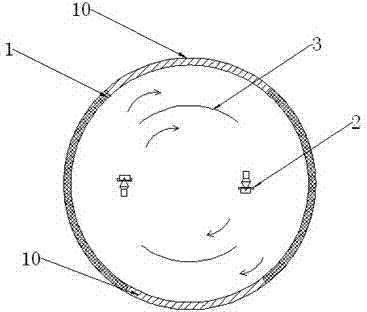
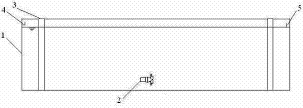
[0056] The adsorption pond used for wastewater treatment described in this embodiment, such as figure 1 with figure 2 shown, including:

[0057] Pool body 1, the pool body 1 is circular; two arc-shaped deflectors 3 are arranged in the pool body, and the two arc-shaped deflectors are respectively concentric with the arc-shaped side walls 10 located on the outside thereof Setting, one end of the pool body 1 is provided with a water inlet 4, preferably the water inlet is arranged on the outside of the arc-shaped deflector 3 in this embodiment, the advantage of such arrangement is that the adsorption effect can be improved, and the water inlet First enter the circulation on the outside of the arc-shaped deflector 3, and then enter the inside of the arc-shaped deflector 3 after being fully mixed with the adsorbent; a water outlet 5 is provided at the other end of the pool body;

[0058] Two pushing flow devices 2 are arranged between a pair of arc-shaped deflectors 3, and the pu...

Embodiment 2

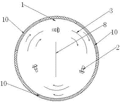
[0066] The adsorption pond used for wastewater treatment described in this embodiment, such as image 3 shown, including:

[0067] Pool body 1, the pool body 1 is circular; three arc-shaped deflectors 3 are arranged in the pool body, and the three arc-shaped deflectors are respectively arranged concentrically with the arc-shaped side walls 10 located on the outside thereof A water inlet 4 is provided at one end of the pool body 1. In this embodiment, the water inlet is preferably arranged on the outside of the arc deflector 3, and a water outlet 5 is provided at the other end of the pool body. ;

[0068] A flow pushing device 2 is arranged between each pair of adjacent arc deflectors 3, and the flow pushing directions of the three flow pushing devices 2 are uniformly arranged in a clockwise direction; the flow pushing device 2 pushes The outflowing liquid flows to the edge of the arc-shaped deflector 3, part of the liquid enters the outside of the arc-shaped deflector 3, and...

Embodiment 3

[0076] The adsorption pond used for wastewater treatment described in this embodiment, such as Figure 4 shown, including:

[0077] Pool body 1, described pool body 1 is provided with four sidewalls, wherein two opposite sidewalls are parallel planar sidewalls 9, and other two opposite sidewalls are arc-shaped sidewalls 10, and the two arc-shaped sidewalls The side wall 10 is curved toward the outside of the pool body 1, and a water inlet 4 is arranged at one end of the pool body. In this embodiment, the water inlet is arranged outside the arc-shaped deflector 3, and the other end is There is a water outlet 5; the maximum length between the two curved side walls 10 of the adsorption pool and the length between the two plane side walls 9 are equal to 3,

[0078] Two arc-shaped deflectors 3, the two arc-shaped deflectors 3 are arranged in the pool body 1, and the inner sides of the two arc-shaped side walls 10 are respectively arranged, and the two arc-shaped deflectors The fl...


PUM

PropertyMeasurementUnit
particle diameteraaaaaaaaaa
concentrationaaaaaaaaaa

Abstract

The invention relates to an adsorption tank. The adsorption tank is characterized in that an arc-shaped guide plate and a flow pushing device are arranged in a tank body, a flow pushing outlet of the flow pushing device faces the edge of the guide plate, a liquid pushed out by the flow pushing device enters the outer side of the arc-shaped guide plate, and remainder pushed out by the flow pushing device enters the inner side of the arc-shaped guide plate. Whether being on the periphery of the arc-shaped guide plate or inside the arc-shaped guide plate, the mixed liquid pushed out by the flow pushing device is entirely at a circular flow state through the flow-pushing effect of the arc-shaped guide plate, and after feed water enters the tank body, the arc-shaped guide plate guides the mixed liquid pushed out by the flow pushing device, so that the flowing of the mixed liquid can be realized by only arranging the few flow pushing devices; and when the adsorption tank with large handling capacity and large size adopts the arrangement mode, the energy consumption is greatly reduced. A clarifier is also arranged on the upper part of the adsorption tank and can be used for rapidly separating water and an adsorbent, so that the land occupied by the adsorption tank is greatly reduced.

Description

technical field [0001] The invention belongs to the field of wastewater treatment, and in particular relates to an adsorption pond for wastewater treatment and a treatment process thereof. Background technique [0002] There are many types of industrial wastewater and the components are very complex. In order to achieve a good treatment effect and realize the recycling of industrial wastewater, biochemical methods are usually used to treat industrial wastewater in the prior art. However, industrial wastewater usually contains a large amount of particulate matter, biodegradable substances and toxic substances. The existence of these substances makes the biodegradable performance of the wastewater worse and affects the treatment efficiency of the subsequent treatment process. Therefore, it is usually necessary to treat the wastewater before biochemical treatment. preprocessing. The adsorption pond is a commonly used wastewater pretreatment structure. By adding adsorbents such...

Claims


Application Information

Patent Timeline
Patent Type & Authority Applications(China)
IPC IPC(8): C02F1/28
Inventor 滕济林曹效鑫李若征赵崇
Owner BEIJING GUODIAN FUTONG SCI & TECH DEV
Learn More