Waterpower self-excited oscillation jet flow vibratory pile sinking device and pile sinking technology

A technology of self-excited oscillating jet and vibratory pile sinking, which is applied in the direction of sheet pile walls, foundation structure engineering, construction, etc., can solve the problems of large damage at the bottom of the pile body, reduced pile sinking efficiency, and unstable pile body, etc., and achieves a solution Pile sinking speed and the problem of breaking through underground obstacles, improving construction efficiency and ensuring the effect of construction quality

Inactive Publication Date: 2013-05-08
东营石大海琛石化科技有限公司 +4
7 Cites 7 Cited by

AI-Extracted Technical Summary

Problems solved by technology

A hydraulic inserting plate and its use method, comprising: (A) lifting a reinforced concrete pile plate with a lifting device, lowering it into the ground through a waterway and a water distribution pipe in the form of hydraulic jetting, and moving the slide plate of another reinforced concrete pile plate from the existing Insert the notched hollow square steel slideway of the pile slab that is lowered into the stratum, and go down into the stratum, including (B) the overall connection between the slabs. Fill with cement slurry to form an inner chamber completely isolated from the outside of the board; (C) Put a grouting pipe into the hollow square steel in the inner chamber, fill the cement slurry from bottom to top, and the entire board The joint between them will form a reinforced concrete overall structure with sandwich steel plates; (D) the top bea...

Method used

About the improvement of water jet hole, existing invention patent No. is ZL200610070402.4 hydraulic plugboard and using method, and water jet hole is electric drill drilling, and the diameter of hole is 2-8mm; And the present invention will multiple The self-excited oscillating nozzle is installed on the jet tube according to the need of cutting the stratum, and the ability of the improved jet tube to cut the stratum is greatly improved.
Compared...

Abstract

The invention relates to a waterpower self-excited oscillation jet flow vibratory pile sinking device and a pile sinking technology. A reinforced concrete pile body is a sheet pile, a square pile head and a hanging ring are arranged in the middle of the top of the reinforced concrete pile body, the reinforced concrete pile body is connected with a vibratory hammer part through a vibratory hammer connecting device, a jet flow pipe with a self-excited oscillation jet flow nozzle is arranged on the bottom of the sheet pile, the jet flow pipe is connected with a high pressure water pump group through a water pipe and rapid docking movable elbows, and the vibratory hammer part is connected with lifting equipment through an integrated lifting appliance. The waterpower self-excited oscillation jet flow vibratory pile sinking device and the pile sinking technology have the advantages that construction technologies of different strata can be resolved, construction efficiency can be improved greatly at the same time, construction quality is guaranteed, drawbacks and defects exist in the prior art are overcome or avoided, the problems of hard clay strata pile sinking speed and breakdown of underground obstacles are resolved, the purpose that undisturbed soil on two 2-meter-long sides of the bottom of the pile body in a pile sinking process is not damaged is achieved, the two sides of the pile body are filled with sand to enable disturbed soil on the two sides of the pile body to be replaced by silver sand, and fast consolidation is achieved.

Application Domain

Technology Topic

RebarSelf excited oscillation +7

Image

  • Waterpower self-excited oscillation jet flow vibratory pile sinking device and pile sinking technology
  • Waterpower self-excited oscillation jet flow vibratory pile sinking device and pile sinking technology
  • Waterpower self-excited oscillation jet flow vibratory pile sinking device and pile sinking technology

Examples

  • Experimental program(1)

Example Embodiment

[0039] Attached Figure 1-16 , To further describe the present invention:
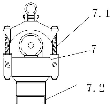
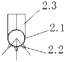
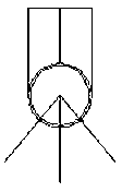
[0040] The hydraulic self-excited oscillating jet vibrating pile sinking device mentioned in the present invention includes a reinforced concrete pile body 1, a jet pipe with a self-excited oscillating jet nozzle 2, a water pipe 3, a quick docking movable elbow 4, and a high-pressure hose 5 , The high-pressure water pump group 6, the vibrating hammer part 7 and the integral spreader 8, the reinforced concrete pile 1 is a sheet pile, with a square pile head 1.3 and a lifting ring 1.5 in the middle of the top, and the vibrating hammer connecting device 7.2 and the vibrating hammer part 7 connection; the two sides of the sheet pile are respectively provided with pile tenon groove 1.1 and pile tenon groove 1.2, the length of the pile tenon groove 1.1 and the pile tenon groove 1.2 is the same as the length of the sheet pile, The inner side of the pile tenon groove 1.1 and the pile concave tenon groove 1.2 are provided with mutually symmetrical semicircular grooves. When two or more sets of sheet piles are connected, a circular channel communicating up and down is formed. There is a water pipe 3; at the bottom of the sheet pile is provided a jet pipe 2 with a self-excited oscillating jet nozzle, which is connected to the high-pressure water pump group 6 through the water pipe 3 and the quick docking movable elbow 4; the vibration The hammer part 7 is connected with the hook of the hoisting equipment 9 through the integral hoisting tool 8.
[0041] Among them, the integral sling 8 is composed of the main sling wire rope 8.1, the auxiliary sling wire rope 8.2, the steering pulley group 8.3, the main sling steel pipe support 8.4, and the hoisting clasp 8.5. The main sling steel pipe support 8.4 is fixed at both ends of the main sling The two ends of the wire rope 8.1 and the main sling wire rope 8.1 are respectively fixed with the hoisting clasp 8.5, and the reinforced concrete pile 1 is fixed by the hoisting clasp 8.5, and the top of the main sling wire rope 8.1 is connected by the main hook 9.1; The middle section of the main sling steel pipe brace 8.4 is fixed with a steering pulley block 8.3, which winds the auxiliary sling wire rope 8.2, the bottom of the auxiliary sling wire rope 8.2 is connected to the vibrating hammer part 7, and the top is connected to the auxiliary hook 9.2.
[0042] Among them, the jet tube 2 with a self-excited oscillating jet nozzle consists of a jet tube 2.1, a self-excited oscillating jet nozzle 2.2, and a self-locking quick coupling 2.3. A plurality of self-excited oscillating jet nozzles 2.2 and a jet tube 2.1 are installed under the jet tube 2.1. A self-locking quick female connector 2.3 is provided at one end of the, and the jet pipe 2.1 is installed at the bottom of the reinforced concrete pile 1 with an inclined angle.
[0043] A hydraulic self-excited oscillating jet vibratory pile driving process includes the following steps:
[0044] First, the tenon grooves on both sides of the reinforced concrete pile are leaned against the grooves on the side of the installed concrete pile, and the soil layer is cut through the strength of the hydraulic self-excited oscillating jet to slowly sink the sheet pile into the ground. , Start the vibratory hammer to speed up the pile sinking speed, when the sheet pile sinks to 2~3m above the design elevation, stop the hydraulic self-excited oscillation jet, at the same time put fine sand 10 in the mud surface gap on both sides of the sheet pile, adopt vibratory pile sinking Continue to sink the sheet piles to the design elevation;
[0045] Second, pressure grouting, inject the fine stone concrete into the circular channel between the two sheet piles through a water pipe. The part below the mud surface is filled with fine stone concrete and then the water pipe is pulled out. The part above the mud surface is grouted with a membrane bag. Stone concrete
[0046] Third, the cast-in-place cap beam, the reserved steel bars on the top of the reinforced concrete sheet piles are uniformly tied to the horizontal steel bars and then cast-in-situ concrete to achieve a horizontal overall connection.
[0047] A hydraulic self-excited oscillating jet vibrating pile sinking process includes the following more specific steps to achieve:
[0048] (1) First install the integral spreader, hydraulic self-excited oscillation jet pipe, water pipe, special elbow for quick docking, water supply hose and vibration hammer;
[0049] (2) When lifting the sheet pile, the sheet pile body should be in a vertical state;
[0050] (3) Start the hydraulic self-oscillation jet system, the jet pipe will jet water downward to cut the stratum, the mud will be discharged along the gap around the sheet pile, and the sheet pile will sink into the stratum under the action of the hydraulic self-excited oscillating jet cutting the stratum and its own gravity;
[0051] (4) Start the electric vibratory hammer to speed up the pile sinking speed. When the sheet pile sinks to 2~3m above the design elevation, stop the hydraulic self-excited oscillation jet, and at the same time put fine sand in the gap between the two sides of the sheet pile. The sheet pile continues to sink to the design elevation, and sand is filled on both sides of the pile body so that the disturbed soil on both sides of the pile body is replaced with fine sand under the action of vibration and quickly consolidated;
[0052] (5) When constructing in areas where the foundation is easy to scour, riprap or riprap feet should be added to ensure the stability of the sheet pile;
[0053] (6) Pressure grouting, twist the water pipe counterclockwise with a lever to make the water pipe separate from the circular channel of the jet pipe, connect the concrete pressure pipe at the top to start the concrete pressure pump, and pour the fine stone concrete between the two piles to squeeze the soft soil , At the same time slowly raise the water pipe, make the part below the mud surface of the two pile joints filled with fine stone concrete, and then pull out the water pipe; grouting the part above the mud surface until the concrete below the mud surface reaches the initial setting state, rinse the joint surface with clean water, adopt The membrane bag is filled with fine stone concrete to fill the circular channel above the mud surface to meet the function of sealing and impermeable joints;
[0054] (7) The cast-in-place cap beam, the reserved steel bars on the top of the sheet pile are uniformly tied to the horizontal steel bars and then the concrete is poured, so as to form a reinforced concrete monolithic continuous wall through horizontal connection.
[0055] Compared with the prior art, the present invention is compared with the traditional concrete sheet pile structure section (foundation manual 15.2.1 Figure 15-3 C) Compared with the increase in the size of the grouting pipe groove in the concave and convex groove, the improvement not only retains the structure of the concave and convex groove, but also enables the pouring of fine stone concrete to be smooth, while leaving space for the water pipeline.
[0056] Compared with the traditional concrete sheet pile technology and the existing invention patent No. ZL200610070402.4 hydraulic insert plate and its use method, a square pile head protruding from the top of the pile is added. After the improvement, the reserved steel bar on the pile top is guaranteed and cast-in-place The cap beam is combined into a whole to solve the installation position of the vibrating hammer connection device.
[0057] Regarding the improvement of the jet tube, the existing invention patent number ZL200610070402.4 hydraulic insert and its use method, the jet tube is installed parallel to the pile end of the sheet pile, and the jet tube of the present invention is installed with a certain inclination angle. When inserted, it can generate thrust to make the sheet pile tightly combined.
[0058] Regarding the improvement of the water jet hole, the existing invention patent number is ZL200610070402.4 hydraulic insert plate and its use method. The water jet hole is drilled by an electric drill, and the diameter of the hole is 2-8mm; and the present invention combines multiple self-excited oscillations The nozzle is installed on the jet tube according to the needs of cutting the formation, and the improved jet tube's ability to cut the formation is greatly improved.
[0059] Regarding the improvement of the water pipe, the existing invention patent number is ZL200610070402.4 hydraulic insert and its use method. The water pipe is installed in the center of the concrete sheet pile; while the present invention installs the water pipe on the end of the pile. The semi-circular structure channel on the side (the side of the groove) retains the original water flow function after improvement, and at the same time serves as a pressure pipe for grouting, and is finally pulled out and reused.
[0060] The invention and use of the quick docking movable elbow has the characteristics that both ends can realize fast docking at the same time, realize multi-angle changes, and a reliable sealing connection device. One end is quickly docked with the water pipe, and the other end is quickly docked with the high-pressure hose. After docking, it can be rotated to release the torque when the hose is compressed. Its use is to increase the efficiency of hydraulic piling preparation by more than 50%.
[0061] The invention and use of the integral spreader solves the problem that the hanging point of the prefabricated sheet pile and the hanging point of the vibrating hammer are in the center position and do not affect each other, simplifies the connecting device of the vibrating hammer and the pile body, and solves the problem that the pile body of the present invention is large and the vibration is selected. Features of small hammer.
[0062] The perfect combination of water jet driving and vibration driving can solve the problem that the original soil on both sides of the pile at the bottom of the pile is destroyed at a depth of two meters during the water jet driving process, thereby avoiding the problem of pile instability; solving the disturbance of the soil on both sides of the pile Replace with fine sand and quickly consolidate.

PUM

no PUM

Description & Claims & Application Information

We can also present the details of the Description, Claims and Application information to help users get a comprehensive understanding of the technical details of the patent, such as background art, summary of invention, brief description of drawings, description of embodiments, and other original content. On the other hand, users can also determine the specific scope of protection of the technology through the list of claims; as well as understand the changes in the life cycle of the technology with the presentation of the patent timeline. Login to view more.

Similar technology patents

Construction method of concrete used for reinforcing underwater pier

Owner:四川路桥建设集团股份有限公司 +1

Classification and recommendation of technical efficacy words

  • Improve construction efficiency
  • Guarantee the construction quality
Why Eureka
Try Eureka