Ocean wave energy generating set

A power generation device and wave energy technology, which is applied in the direction of ocean power generation, hydropower generation, engine components, etc., can solve the problems of reducing power generation efficiency, gear surface wear, synchronous belt out of sync, etc., to improve power generation efficiency and anti-sediment effect Strong, good service life effect

Inactive Publication Date: 2013-05-08
于传祖
View PDF7 Cites 16 Cited by
  • Summary
  • Abstract
  • Description
  • Claims
  • Application Information

AI Technical Summary

Problems solved by technology

This device uses the thrust of the ocean currents on the blades to generate electricity, which can achieve a relatively good power generation function, but there is a certain impact in the actual use process, which is mainly manifested in the impact between the blade and the T-shaped bracket when the blade changes direction. , at the same time, the pulley will turn over twice every revolution, and the wear is serious
[0003] Another example is "A Vertical Axis Rhombus Fluid Kinetic Power Generation Conversion Device" published by Chinese patent 201010549418X, which discloses functional components such as frame, gear, synchronous belt, synchronous shaft and blades. During the operation of the device to generate electricity, there are still The following problems, first, the timing belt and the gear rely on the meshing of the two to achieve synchronous operation. During the long-term operation, the upper and lower timing belts have a problem of asynchrony, which causes the deflection of the blades and affects the stress state of the blades. Reduce power generation efficiency; second, ocean currents contain sediment, and sand particles entering between the synchronous belt and the gears will cause wear on the surface of the gears; The first is to use the horizontal thrust of the ocean current to push the blades to do work. The fourth is that the ocean current is an elliptical ocean current with an uncertain direction. When the direction of the ocean current is not perpendicular to the face of the device, it is easy to cause the timing belt to fall off.

Method used


Image

  • Ocean wave energy generating set
  • Ocean wave energy generating set
  • Ocean wave energy generating set

Examples


Embodiment Construction

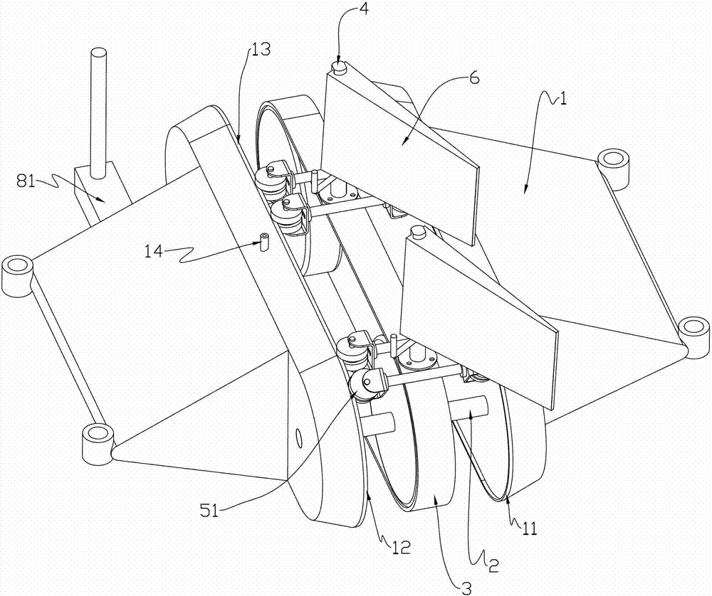
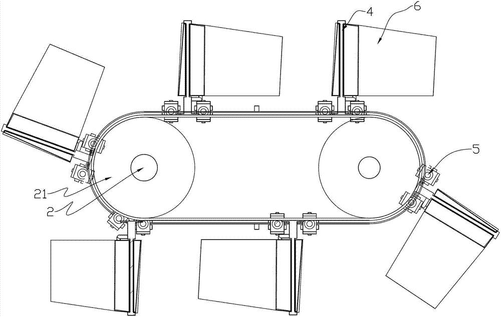
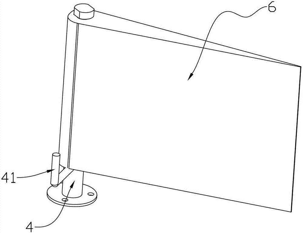
[0029] Such as Figure 1 to Figure 5 As shown, an ocean wave energy generating device includes a generator, a pulley shaft, a belt, blades, a bracket and a breakwater. Generators are power generating equipment and are installed in place.

[0030] The wedge-shaped breakwaters 1 are arranged in pairs, and the periphery of the breakwater 1 is provided with a circular track 11. The circular track 11 is a non-impact track composed of parabolic segments 12 at both ends and a straight line segment 13 in the middle. The breakwater is a hollow structure, and the shell of the breakwater is provided with an air charging and discharging port 14, and the lower side is provided with an inlet and a drain port. Pulley shafts 2 are installed between the breakwaters 1, and the pulley shafts 2 are arranged in pairs, and the generator is driven by one of the pulley shafts to generate electricity. A rubber pneumatic tire 21 is fixed in the middle of the pulley shaft 2. The rubber pneumatic tire ...


PUM


Abstract

The invention discloses an ocean wave energy generating set, and solves the problem that an existing power generation device cannot operate continuously without impact. The ocean wave energy generating set comprises a generator, belt wheel shafts, a belt, blades and supports. The generator is driven by the belt wheel shafts to generate electricity. The supports are mounted on the belt, and the blades are mounted on the supports. The ocean wave energy generating set is characterized by further comprising wedge-shaped waving dykes which are arranged in pairs, wherein at least two belt wheel shafts are mounted between the waving dykes in a parallel mode, rubber air-filled tires are arranged on the belt wheel shafts, the belt is placed between the rubber air-filled tires in a sleeved mode, a track guiding mechanism is arranged between each waving dyke and the belt, and each support is provided with a limiting stop block used for limiting the front-back swing angle of the blade on the support along a track surface of the belt. The ocean wave energy generating set is good in comprehensive performance and takes overall consideration of multiple factors such as manufacture, installation, maintenance and long-term power generation.

Description

technical field [0001] The invention relates to the technical field of ocean power generating devices, in particular to an ocean wave energy generating device. Background technique [0002] The applicant applied for an invention patent for an ocean current power generation device in 2011, the application number is 2011102370993, which discloses part of the structure, mainly including generators, pulleys, belts, blades and T-shaped brackets, where the generator is driven by the pulley. To generate electricity, a T-shaped bracket is installed on the belt, blades are installed on the T-shaped bracket, and the blades and the T-shaped bracket are connected through hinges. When the device is in use, the belt is arranged along the direction of the ocean current, the upper blades are perpendicular to the direction of the ocean current and do useful work under the push of the ocean current, and the lower blades are parallel to the direction of the ocean current and return against the...

Claims


Application Information

Patent Timeline
Patent Type & Authority Applications(China)
IPC IPC(8): F03B13/20F03B13/26
CPCY02E10/38Y02E10/28Y02E10/30Y02P70/50
Inventor 于传祖
Owner 于传祖
Why Eureka
Try Eureka