Scroll compressor

A scroll compressor and moving scroll technology, applied in the field of scroll compressors, can solve problems such as poor effect and poor lubrication of moving scroll bearings, achieve obvious cooling effect, solve poor lubrication bearing burn, reduce burn The effect of the bearing

Inactive Publication Date: 2013-05-08
LIUZHOU YIZHOU AUTOMOBILE AIR CONDITIONER
View PDF5 Cites 7 Cited by
  • Summary
  • Abstract
  • Description
  • Claims
  • Application Information

AI Technical Summary

Problems solved by technology

[0003] The purpose of the present invention is to provide a scroll compressor, which can solve the problem of poor lubrication and poor effect of the orbiting scroll bearing

Method used


Image

  • Scroll compressor
  • Scroll compressor
  • Scroll compressor

Examples


Embodiment 1

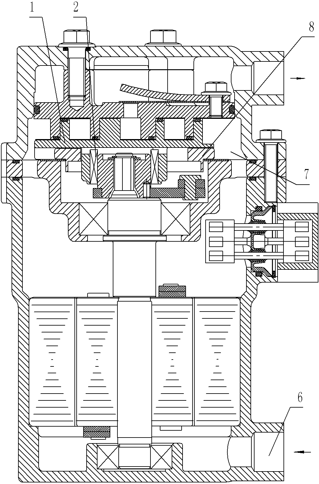
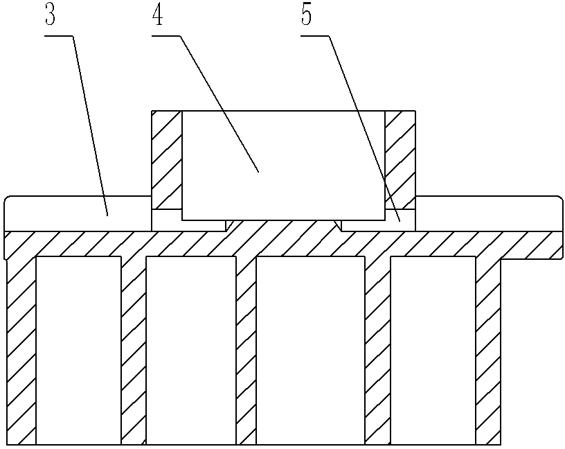
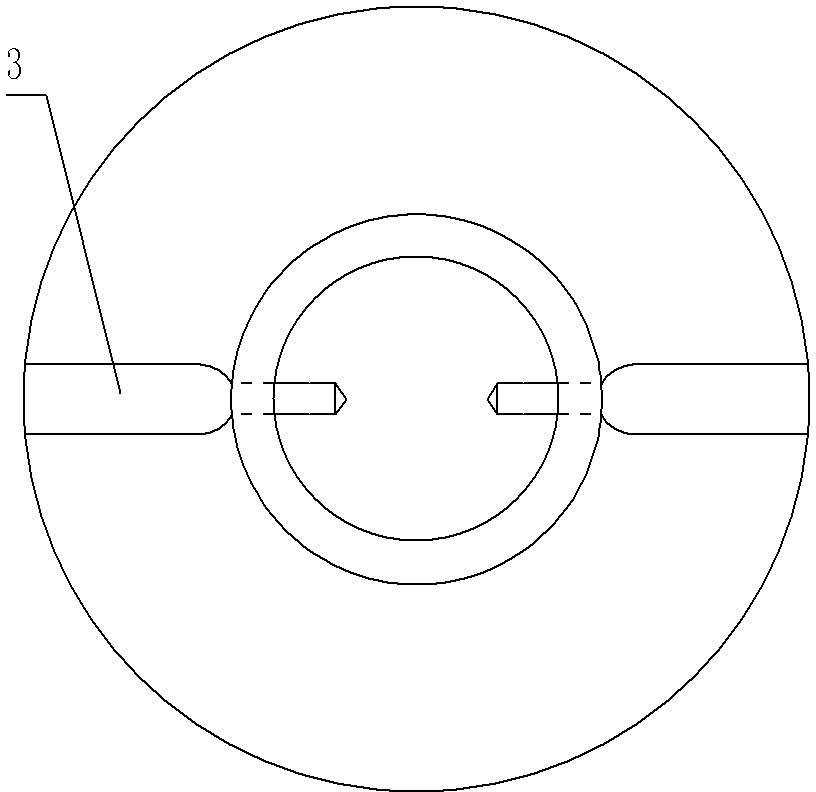
[0018] figure 1 The scroll compressor shown includes a movable scroll 1 and a bearing 2 installed in the bearing seat hole 4 on the back side of the movable scroll 1. The back end surface of the movable scroll 1 is provided with a slip ring outside the bearing seat part. Slot 3, as in figure 2 , image 3 As shown, the orbiting scroll 1 is provided with a channel 5 connecting the slip ring groove 3 and the bearing housing hole 4; the channel 5 is a circular hole axially parallel to the slip ring groove 3, and the diameter of the circular hole is preferably 3 to 8 mm, the diameter of the round hole of the passage 5 in this embodiment is 5.5 mm; there are two round holes of the passage 5, which are located on the side wall of the bearing seat hole 4, and respectively connected to the back end surface of the movable scroll 1 The two slip ring grooves 3 on the outside of the bearing housing part communicate.

Embodiment 2

[0020] figure 2 , image 3 As shown, the orbiting scroll 1 is provided with a channel 5 connecting the slip ring groove 3 and the bearing seat hole 4; the channel 5 is a circular hole axially parallel to the slip ring groove 3, and the diameter of the circular hole of the channel 5 is 3 mm; All the other features are the same as in Example 1.

Embodiment 3

[0022] figure 2 , image 3 As shown, the orbiting scroll 1 is provided with a channel 5 connecting the slip ring groove 3 and the bearing seat hole 4; the channel 5 is a circular hole axially parallel to the slip ring groove 3, and the diameter of the circular hole of the channel 5 is 8 mm; All the other features are the same as in Example 1.

[0023] When working, the refrigerant mixed with lubricating oil enters from the suction port 6 of the scroll compressor, enters the chamber 7 from the inner wall passage of the casing, and the slip ring 8 reciprocates in the slip ring groove 3 relative to the movable scroll 1, The refrigerant mixed with lubricating oil enters the bearing seat hole 4 from the channel 5 of the bearing seat hole 4 to lubricate and cool the bearing 6 installed therein, and then exits from the channel 5 on the other side.


PUM


Abstract

The invention discloses a scroll compressor, relating to the technical field of manufacturing of fluid machinery. The scroll compressor comprises a movable scroll plate, a static scroll plate and bearings installed in a bearing carrier on the back surface of the movable scroll plate, wherein the static scroll and the movable scroll mesh with each other to form a variable-volume compression chamber. The invention is characterized in that at least two groups of through holes are drilled from the inner end of a slip ring groove at the back end surface of the movable scroll plate to the inner cavity of the bearing carrier, so that lubricating oil outside the movable scroll plate can smoothly enter the inner cavity of the bearing carrier of the movable scroll plate. Compared with the prior art, the invention can enable the lubricating oil outside the bearing carrier of the movable scroll plate to enter the inner cavity of the bearing carrier through the drilled channels, so that the bearings installed in the bearing carrier can be sufficiently cooled and lubricated, thereby greatly reducing the phenomenon of bearing burnout caused by bearing overheating due to defective lubrication or oil shortage of the bearings.

Description

technical field [0001] The invention relates to the technical field of fluid machinery manufacturing, in particular to a scroll compressor with a movable scroll. Background technique [0002] The scroll compressor realizes the compression of gas through the relative meshing motion of the movable and fixed scrolls. The movable scroll is driven by the eccentric main shaft, and the fixed scroll and the movable scroll form a closed compression chamber. When the movable scroll rotates around the fixed scroll, the volume of the closed compression chamber formed by the fixed and movable scrolls changes from large to small. The center of the fixed scroll is provided with an exhaust port, and the compressed gas is discharged from the exhaust port. Port discharge, so as to realize the scroll compressor suction, compression and exhaust the whole process. There is a bearing seat on the back of the movable scroll, and the inner hole is equipped with a bearing that rotates with the movab...

Claims


Application Information

Patent Timeline
Patent Type & Authority Applications(China)
IPC IPC(8): F04C18/02F04C29/00F04C29/02F04C29/04
Inventor 张建场潘煜
Owner LIUZHOU YIZHOU AUTOMOBILE AIR CONDITIONER
Why Eureka
Try Eureka