Pressure vessel valve

A pressure vessel and valve body technology, applied in the field of pressure vessel valves, can solve problems such as mis-opening of the handwheel, and achieve the effects of avoiding mis-opening, long service life, and improving the limit effect.

Active Publication Date: 2015-01-14
南京华兴压力容器制造有限公司
View PDF6 Cites 0 Cited by
  • Summary
  • Abstract
  • Description
  • Claims
  • Application Information

AI Technical Summary

Problems solved by technology

[0004] The disadvantage of the above-mentioned pressure vessel valve in the prior art is that the hand wheel is easily opened by human or other means of misoperation, how to avoid this situation is a technical problem to be solved in this field

Method used


Image

  • Pressure vessel valve
  • Pressure vessel valve
  • Pressure vessel valve

Examples


Embodiment Construction

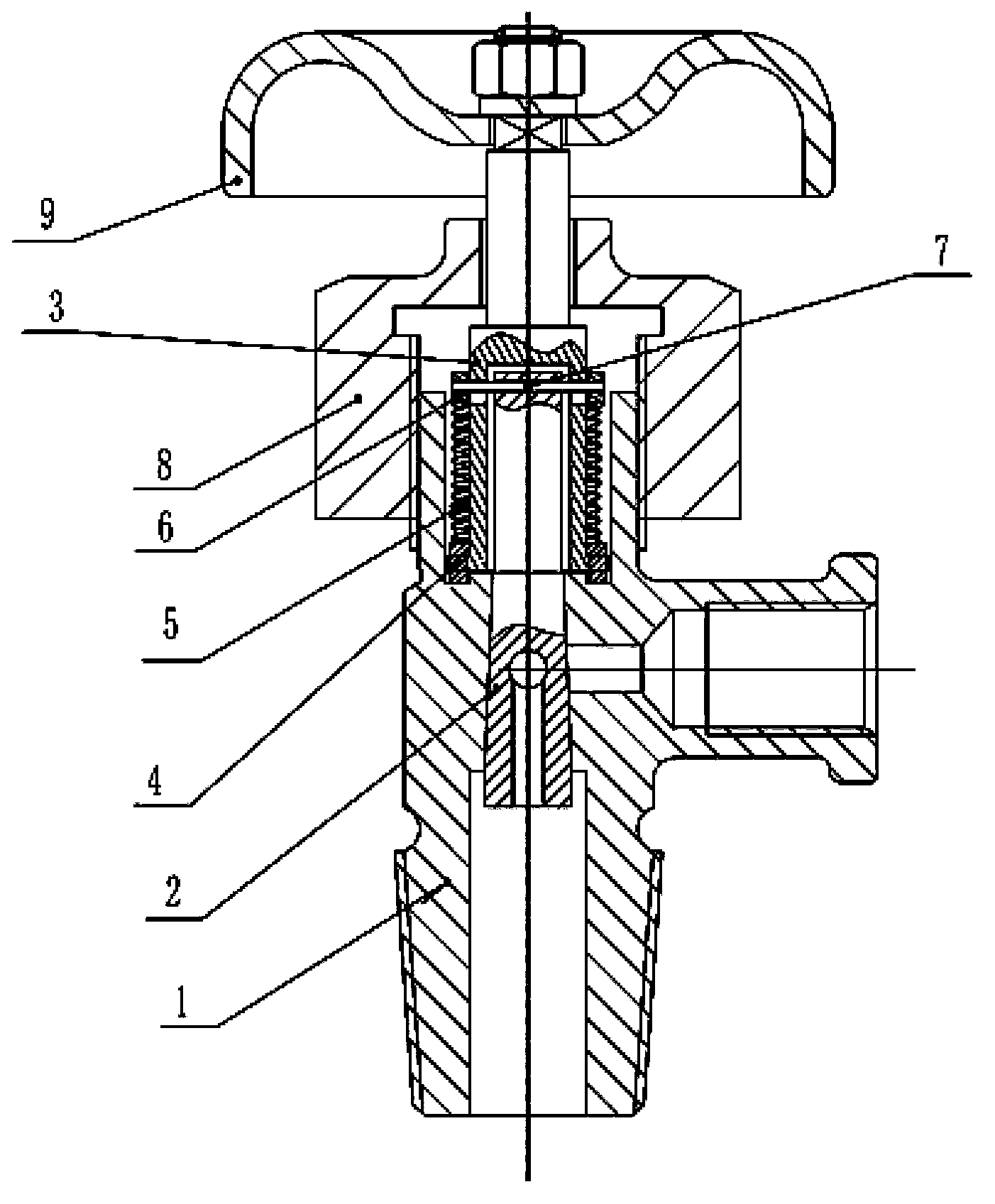
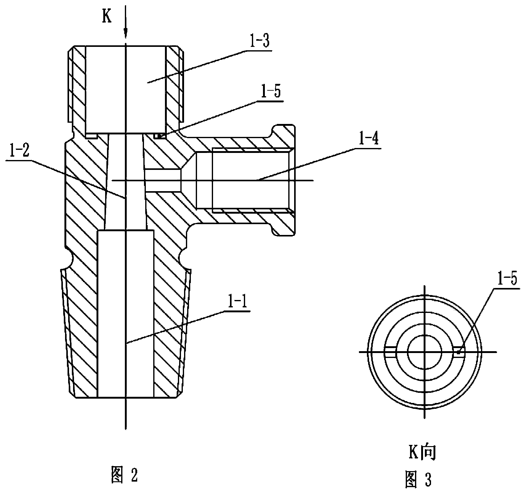
[0024] See Figure 1-10 , the pressure vessel valve suitable for automatic locking in this embodiment includes: a valve body 1, a valve stem 2 arranged in the valve body 1, a lock lever 3 arranged at the upper end of the valve stem 2, and a hand lever arranged at the top of the lock lever 3. Wheel 9; valve stem 2 includes: conical section 2-1 and cylindrical section 2-2 connected to the upper end of the conical section 2-1; valve body 1 includes: the first cylindrical cavity 1-1 at the bottom, the same A conical cavity 1-2 with an axis set at the upper end of the first cylindrical cavity 1-1, which is suitable for sealing fit with the conical section 2-1 of the valve stem 2, and a coaxial line set at the conical cavity The second cylindrical cavity 1-3 at the upper end of 1-2; the side wall of the conical cavity 1-2 is provided with an exhaust port 1-4; the diameter of the upper port of the conical cavity 1-2 is smaller than the second cylindrical cavity 1-3 in diameter to fo...


PUM


Abstract

The invention relates to a pressure vessel valve which is simple in structure, better in security and reliability, capable of avoiding being opened by mistake, and suitable for automatic locking. The pressure vessel valve comprises a valve body, a valve rod, a locking rod and a hand wheel. The valve rod comprises a conical section and a cylindrical section. The valve body comprises a first cylindrical cavity, a conical cavity and a second cylindrical cavity. The diameter of the upper port of the conical cavity is smaller than that of the second cylindrical cavity. An annular platform is formed on the bottom portion of the second cylindrical cavity, and a locking groove is formed in the annular platform. A tube body of the middle and lower section of the locking rod is arranged on the cylindrical section of the valve rod in a sleeved mode, and a pair of waist-shaped holes is formed in the middle and upper portion of the tube body in the radial. A spring pin is arranged in the pin hole of the locking rod and two ends of the spring pin stretch out of the pair of waist-shaped holes. An annular boss is arranged on the bottom of the locking rod. An annular locking pin which is arranged on the tube body in a sleeved mode is arranged at the upper end of the annular boss. A pressing ring is arranged at the lower end of a spring pin. A spring is arranged between the pressing ring and the annular locking pin. A protrusion which is suitable for being matched with the locking groove is arranged on the lower end surface of the annular locking pin.

Description

[0001] This application is a divisional application, the application number of the original application is: 201110086790.6, the application date: 2011-04-07, and the title of the invention is "Pressure Vessel Valve Suitable for Automatic Locking". technical field [0002] The invention relates to a pressure container valve suitable for automatic locking, which is suitable for metal containers of liquefied pressure gases such as liquefied petroleum gas, coal gas, dimethyl ether and natural gas. Background technique [0003] Existing pressure vessel valves include: a valve body, a tapered valve stem that is sealingly fitted in the valve body and a handwheel connected to the top of the valve stem. The side wall of the valve body is provided with an exhaust port, and the lower end of the valve stem is axial There is a vent hole, which communicates with the vent port on the side wall of the valve stem; when the vent port on the side wall of the valve stem is in the same direction ...

Claims


Application Information

Patent Timeline
Patent Type & Authority Patents(China)
IPC IPC(8): F16K5/02F16K31/44F16K35/02
Inventor 徐茂航
Owner 南京华兴压力容器制造有限公司
Why Eureka
Try Eureka