Direct-type sewage source heat pump device

A sewage source heat pump and sewage technology, applied in heat pump, heating method, household heating and other directions, can solve problems such as energy loss, reduce heat pump energy efficiency ratio, high sewage viscosity, etc. The effect of reducing and reducing energy consumption

Active Publication Date: 2013-05-08
HIT HARBIN INST OF TECH KINT TECH
View PDF6 Cites 3 Cited by
  • Summary
  • Abstract
  • Description
  • Claims
  • Application Information

AI Technical Summary

Problems solved by technology

[0023] 2. The direct sewage source heat pump unit needs special treatment, which is technically difficult
[0024] 3. The direct system requires a major modification of the evaporator / condenser of the heat pump unit, and there are few corresponding unit manufacturers
[0027] Due to the high viscosity of sewage and low heat transfer coefficient, the sewage heat exchanger must be made very large; when sewage is used as the cold and heat source of the heat pump, the sewage must be purified and passed through an additional sewage / water heat exchanger in front of the unit , to transfer the heat or cold of the sewage to the intermediate water of the heat pump, this process will cause energy loss and reduce the energy efficiency ratio of the heat pump
If the sewage is not strictly purified and directly enters the heat pump without passing through the sewage / water heat exchanger, the sewage and the refrigerant directly exchange heat, and the sewage circulation pipeline in the heat pump is usually blocked very quickly, so that the heat pump cannot work at all

Method used


Image

  • Direct-type sewage source heat pump device
  • Direct-type sewage source heat pump device
  • Direct-type sewage source heat pump device

Examples


Embodiment Construction

[0063] The present invention will be described in further detail below in conjunction with the drawings and embodiments.

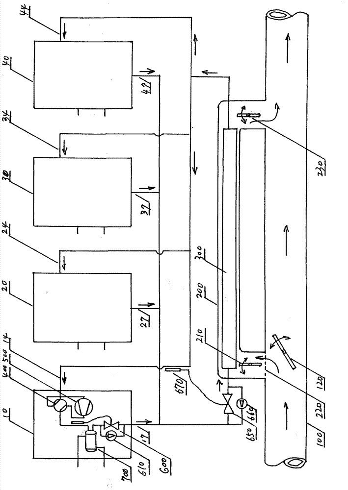
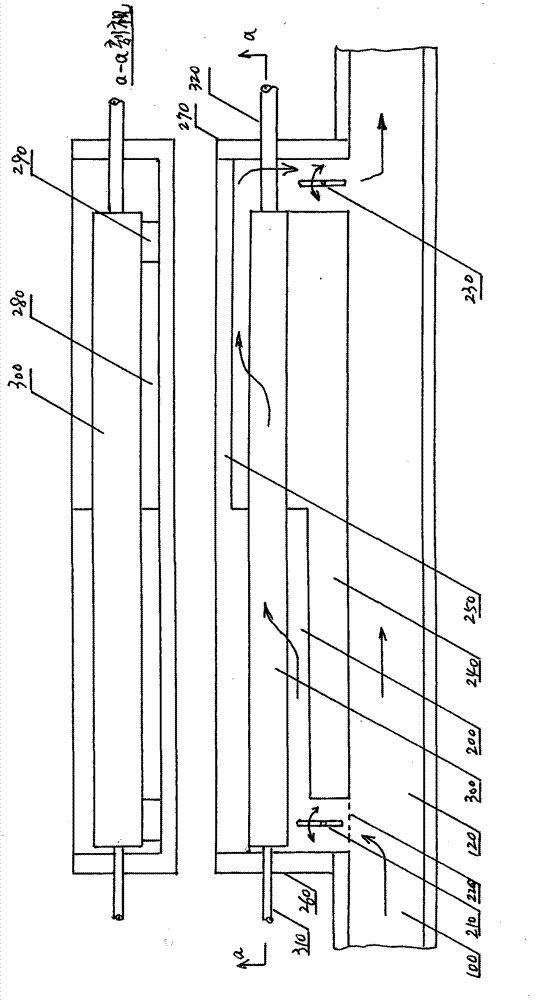
[0064] figure 1 The overall structure diagram of the embodiment of the direct sewage source heat pump device of the present invention is given.

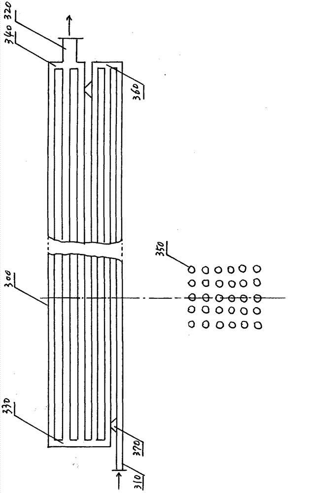
[0065] The overall structure of the embodiment of the direct sewage source heat pump device of the present invention includes: a heat pump host 10, a heat pump host 20, a heat pump host 30, a heat pump host 40, a throttle valve 650, a one-way valve 660, an online sewage / freon heat exchanger 300 and Sinkhole 200. Among them, the heat pump host 10, the heat pump host 20, the heat pump host 30, and the heat pump host 40, the four heat pump hosts have the same structure, and they work in parallel. The number of heat pump hosts may not be four, and the specific number is not limited, but they all work in parallel.

[0066] The embodiment of the direct sewage source heat pump device of the present invention can be used for ...


PUM


Abstract

The invention provides a direct-type sewage source heat pump device which comprises a plurality of main heat pump machines, an on-line / freon heat exchanger, a throttle valve, a one-way valve and a sewage tank. During operation of heat supply, sewage serves as a heat source, the on-line / freon heat exchanger placed in the sewage tank serves as an evaporator, liquid freon flowing out of the main heat pump machines flows into the evaporator through the one-way valve and the throttle valve to obtain heat from the evaporator and then is evaporated into steam to enter into the main heat pump machines so as to transfer heat to circulating water, and the circulating water supplies the heat to a user; during refrigeration operation, sewage serves as a cold source, the on-line / freon heat exchanger serves as a condenser, freon steam flowing out of the main heat pump machines enters into the condenser for condensation and transfers heat to sewage, liquid freon flows out of the condenser and enters the main heat pump machines through the one-way valve to transfer cold to the circulating water, and the circulating water supplies the cold for the user; and the on-line / freon heat exchanger can be simultaneously used as the evaporator or the condenser of the plurality of main heat pump machines.

Description

Technical field [0001] The invention relates to heat pump technology, in particular to a direct sewage source heat pump device. Background technique [0002] Sewage source heat pump relies on the cyclical change of the refrigerant inside the heat pump unit. In winter, it absorbs heat from the sewage and heats the building after the heat pump unit heats up; in summer, the heat pump unit transfers the heat in the building to the sewage to achieve For cooling, sewage replaces the cooling tower. [0003] Using urban sewage as a cold and heat source to heat and air-condition buildings can reduce energy consumption. The sewage source heat pump realizes the recycling and utilization of urban waste heat and turning waste into treasure. It is an important measure for resource recycling, development of a circular economy, and building a conservation-oriented society and a friendly environment. It is a new type of renewable and clean energy utilization technology that meets the requirements...

Claims


Application Information

Patent Timeline
IPC IPC(8): F24F5/00F25B30/06
Inventor 尚德敏李金峰李伟张勇
Owner HIT HARBIN INST OF TECH KINT TECH
Why Eureka
Try Eureka