Method for controlling furnace pressure of pulse furnace

A furnace pressure control and pulse furnace technology, which is applied in the direction of furnace control devices, furnaces, furnace components, etc., can solve the problems of walking beams affecting the atmosphere in the furnace, poor portability, and occupation of self-learning functions.

Active Publication Date: 2013-05-08
SHANGHAI BAOSIGHT SOFTWARE CO LTD
View PDF4 Cites 9 Cited by
  • Summary
  • Abstract
  • Description
  • Claims
  • Application Information

AI Technical Summary

Problems solved by technology

[0003] 1) The periodic movement of the walking beam seriously affects the atmosphere in the furnace;
[0004] 2) The furnace door design of the slab heating furnace is much larger than that of the rod and wire heating furnace, and frequent opening and closing has a great influence on the furnace pressure;
[0005] 3) Due to the characteristics of pulse combustion technology, frequent pulse switching has a great impact on the air flow in the furnace;
[0016] 1) The establishment of the fuzzy query table is relatively difficult;
[0017] 2) The self-learning function takes up a lot of system resources and is not stable;
[0018] 3) Poor portability
[0021] 1) The soaking section adopts conventional control, and the burner type and control method are different from pulse combustion, which increases additional cost and workload;
[0022] 2) The soaking section adopts conventional control, which loses the advantage of pulse combustion;
[0023] 3) The soaking section adopts conventional control, which increases the hysteresis characteristic of furnace pressure adjustment

Method used


Image

  • Method for controlling furnace pressure of pulse furnace
  • Method for controlling furnace pressure of pulse furnace

Examples


Embodiment Construction

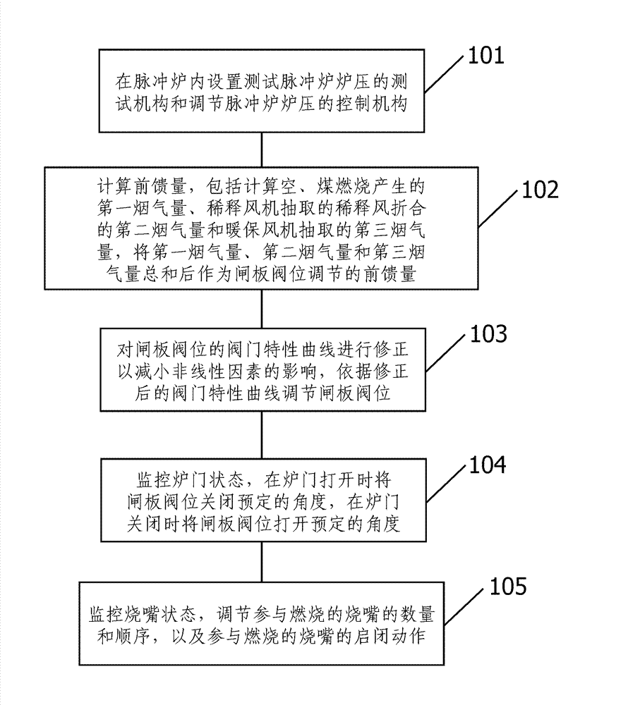
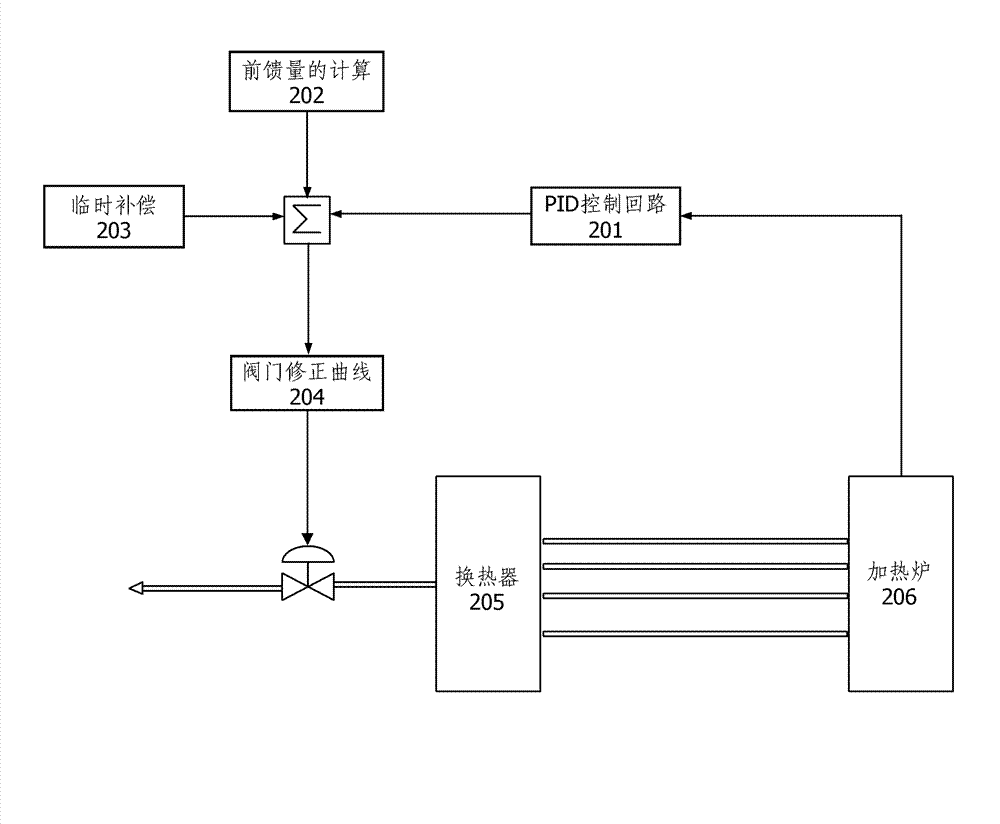
[0036] According to the actual investigation, analysis and test of the working process of the pulse furnace, the present invention finds that the furnace pressure control strategy of PID+feedforward control+temporary compensation can effectively realize the stable control of the furnace pressure. The advantage of this combined control strategy is that it not only retains the accuracy of PID control but also reflects the rapidity of feedforward control. Temporary compensation makes the valve move in advance to reduce the influence of disturbance factors on furnace pressure.

[0037] The root of controlling the furnace pressure of a pulse furnace lies in how to balance the relationship between the flue gas variation in the furnace and the opening of the gate valve position. After analysis, it is found that the disturbance factors affecting the furnace pressure mainly include: burner logarithm, combustion capacity, gate valve Position characteristics, the position of the pressure ...


PUM


Abstract

An embodiment of the invention discloses a method for controlling the furnace pressure of a pulse furnace. The method includes the steps: arranging a test mechanism for testing the furnace pressure of the pulse furnace and a control mechanism for adjusting the furnace pressure of the pulse furnace in the pulse furnace; calculating feed-forward quantities including a first flue gas quantity, a second flue gas quantity and a third flue gas quantity and then summarizing the first flue gas quantity, the second flue gas quantity and the third flue gas quantity to serve as the adjusting feed-forward quantity of a gate valve position; correcting a valve characteristic curve of the gate valve position to reduce the influence of nonlinear factors, and adjusting the gate valve position according to the corrected valve characteristic curve; monitoring the state of a furnace door, closing the gate valve position by a preset angle when the furnace door is opened, and opening the gate valve position by the preset angle when the furnace door is closed; and monitoring the state of burners, and adjusting the number, the sequence and opening-closing action of the burners involved in combustion. The control mechanism comprises the adjustable gate valve position, first flue gas is generated by air and coal combustion, second flue gas is reduced by dilution wind extracted by a dilution fan, and third flue gas is extracted by a warm protection fan.

Description

technical field [0001] The invention relates to the control technology of a pulse furnace, in particular to a furnace pressure control method of a pulse furnace. Background technique [0002] In November 1997, Stein applied the pulse technology to the slab heating furnace for the first time. In China, the all-digital pulse furnace has been applied in a few steel plants. In the actual application process, the pulse furnace is It has played a positive role in improving thermal efficiency, reducing energy consumption, and improving the uniformity of the temperature field in the furnace. However, due to the discontinuous nature of pulse combustion, the air flow in the furnace is unstable and the furnace pressure fluctuates greatly. The main disturbance of furnace pressure Factors are: [0003] 1) The periodic movement of the walking beam seriously affects the atmosphere in the furnace; [0004] 2) The furnace door design of the slab heating furnace is much larger than that of ...

Claims


Application Information

Patent Timeline
Patent Type & Authority Applications(China)
IPC IPC(8): F27D19/00
Inventor 李凤召张凌
Owner SHANGHAI BAOSIGHT SOFTWARE CO LTD
Why Eureka
Try Eureka