Point location installation method for foot support of thermal radiation tube

A technology of a heat radiation tube and an installation method, which is applied to measurement devices, instruments, surveying and mapping, and navigation, etc., can solve problems such as large measurement workload, achieve high positioning accuracy, improve construction efficiency, and reduce measurement and calculation workload.

Active Publication Date: 2015-06-24
ANGANG CONSTR CONSORTIUM
View PDF4 Cites 0 Cited by
  • Summary
  • Abstract
  • Description
  • Claims
  • Application Information

AI Technical Summary

Problems solved by technology

[0003] The disadvantage of this technical solution is that there is a large amount of measurement work in the actual construction: 1) After using the U-shaped template to measure and mark the vertical centerline of the installation datum square window, it is also necessary to sort the marked line segments For measurement and data statistics, mark the installation position of each foot support on the inner wall of the furnace shell; 2) use a ruler and a precision level to carry out the projection and positioning of the center horizontal line of the opposite window, and measure and mark the foot on the inner wall of the furnace shell The horizontal line of the center of the support, because the position of the horizontal center line of the opposite window of the precision level is limited by the width of the steel walking platform, the precision level is in the state of measuring the horizontal inclination of the position of the support, so a large amount of additional calculation workload is generated

Method used


Image

  • Point location installation method for foot support of thermal radiation tube
  • Point location installation method for foot support of thermal radiation tube

Examples


Embodiment Construction

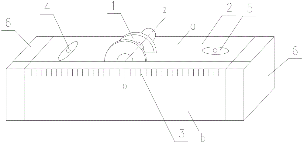
[0017] The specific embodiment of the present invention will be further described below in conjunction with accompanying drawing:

[0018] See figure 1 , is a structural schematic diagram of an embodiment of a combined laser unloading instrument of the present invention, including a laser emitting head 1, a horizontal bubble 4, a horizontal bubble 2 5 and a square bracket 2, the laser beam emitting axis z of the laser emitting head 1 and the square bracket The central position of the scale scale 3 of the frame 2 corresponds to and is parallel to the upper plane a of the square bracket 2, and perpendicular to the front side b of the square bracket 2. The upper plane a of the square bracket 2 is also provided with a horizontal bubble 4 and a horizontal bubble 2 5 , the length direction of horizontal bubble 1 4 is parallel to the width direction of plane a on the square bracket 2, the length direction of horizontal bubble 2 5 is parallel to the length direction of plane a on the ...


PUM


Abstract

The invention relates to the field of industrial installation technology of vertical type continuous annealing furnace, and particularly relates to a point location installation method for a foot support of a thermal radiation tube. The point location installation method is characterized by comprising the following operational steps of 1) determining a pay-off height datum line X11 on installation reference rectangular windows; 2) center-placing a combined laser pay-off instrument on a flange of each rectangular window horizontally, forming a central cross projection point since laser beams Z projects on wall board planes in a furnace shell; 3) welding a temporary positioning elevation angle iron; 4) repeating the steps of 2) and 3), and thus the installation positioning centers of all the foot supports of the thermal radiation tube can be positioned. Compared with a conventional method, the point location installation method has the beneficial effects that the step of establishing a three-dimensional rectangular coordinate system for coordinate central points of a structure installation part so as to measure and mark is omitted, the position can be fixed at one time directly and quickly, measurement calculation workload can be reduced, positioning accuracy is high and meets the requirement of construction quality, the qualified rate of installation reaches 100%, and construction efficiency is increased by three times.

Description

technical field [0001] The invention relates to the technical field of industrial installation of a vertical continuous annealing furnace, in particular to a point-positioning installation method of a heat radiation tube support. Background technique [0002] The existing patent technology discloses an installation method of heat radiation pin support, patent number ZL200810011694.3, the centerline positioning method of the heat radiation pin support used in this invention is: first, use a precision theodolite and a precision level Establish a three-dimensional Cartesian coordinate system; secondly, use a ruler and a U-shaped template marked with a scale to measure the horizontal centerline and vertical centerline of the opposite window; then, use the ruler and a precision level to measure the vertical centerline and horizontal centerline of the opposite window respectively. Locate the line marking, measure and mark the center line of the foot support. U-shaped templates ma...

Claims


Application Information

Patent Timeline
Patent Type & Authority Patents(China)
IPC IPC(8): G01C15/00
Inventor 姜长平邵波吴岩
Owner ANGANG CONSTR CONSORTIUM
Why Eureka
Try Eureka