Transducer capable of being directly applied to various ultrasonic flow meters

An ultrasonic and transducer technology, applied in the field of transducers, can solve problems such as poor anti-corrosion, anti-impurity and anti-fouling effects, maintenance and replacement shutdown processing, failure of measurement equipment, etc., to achieve stable and reliable sampling signals, The effects of excellent pressure-bearing performance and durability, and excellent acoustic-electric matching performance

Active Publication Date: 2013-05-08
DALIAN HUANDAO INSTR +2
View PDF7 Cites 6 Cited by
  • Summary
  • Abstract
  • Description
  • Claims
  • Application Information

AI Technical Summary

Problems solved by technology

Most of the existing ultrasonic flowmeters are fixed and installed during on-site equipment assembly, and the assembly and debugging must be done before installation. Once damaged, maintenance and replacement need to be shut down.
In addition, the existing ultrasonic flowmeter itself has poor anti-corrosion, anti-impurity, and anti-fouling effects. Additional protection devices are required to prevent the ultrasonic flowmeter from being damaged too quickly when it is used in a relatively corrosive liquid medium. It brings disadvantages such as complicated installation process and high maintenance cost
Especially in the actual use process, due to the influence of temperature and pressure changes, the transducer will cause serious cracks in the piezoelectric ceramic sheet, which will lead to the inability to sample and cause the function of the entire measurement equipment to fail. Once this phenomenon occurs, the entire measurement equipment Or the instrument will not work, and the entire measuring device or instrument must be replaced when the operation is stopped, resulting in serious losses. This is a major problem that has plagued the field of ultrasonic measurement applications for many years.

Method used


Image

  • Transducer capable of being directly applied to various ultrasonic flow meters
  • Transducer capable of being directly applied to various ultrasonic flow meters
  • Transducer capable of being directly applied to various ultrasonic flow meters

Examples


Embodiment Construction

[0026] Embodiments of the present invention will be described below with reference to the drawings. In this specification, in order to simplify the description, words used to describe the positional and directional relationship between corresponding components, such as upper, lower end, inner, outer, top and bottom, only refer to the positional relationship and direction in the drawings.

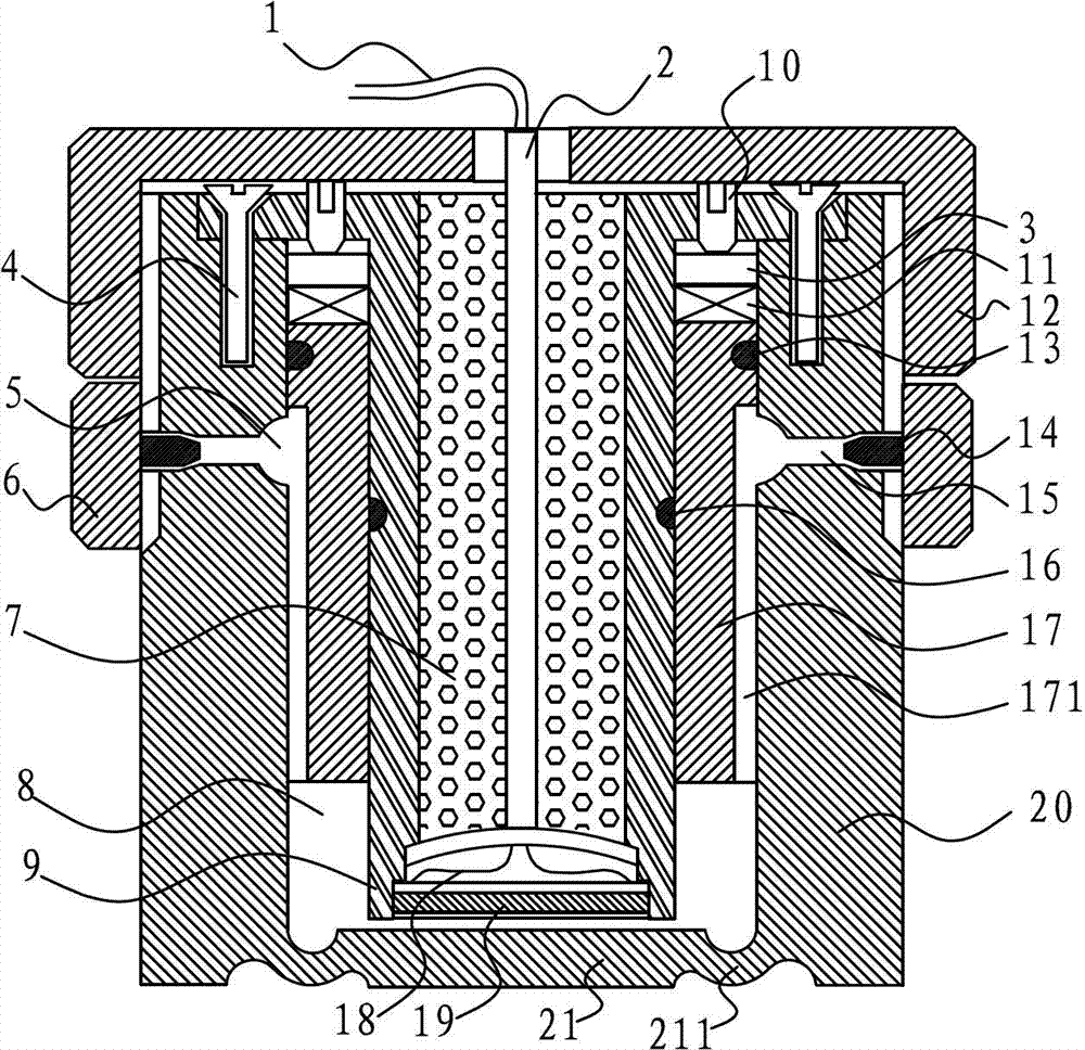
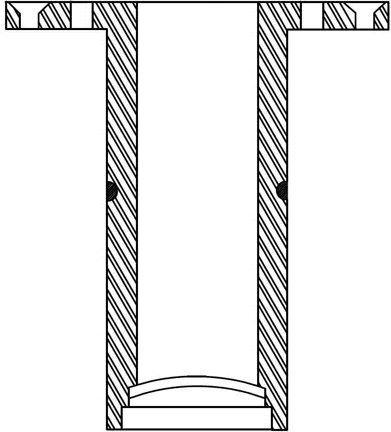
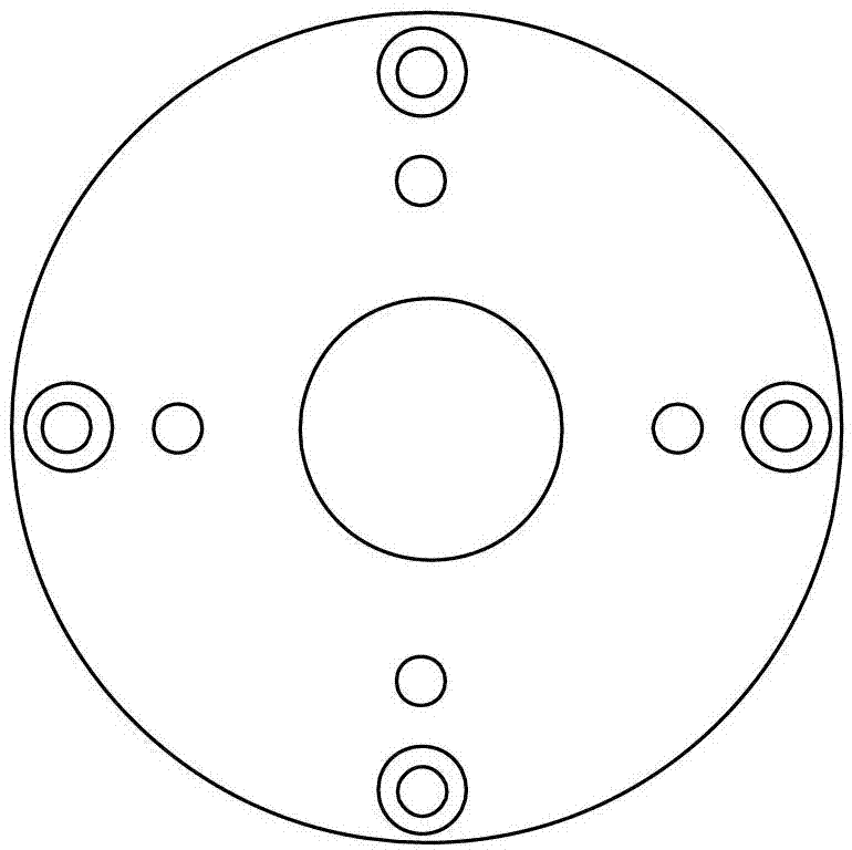
[0027] Such as Figure 1 to Figure 5 The shown transducer directly applied to a variety of ultrasonic flowmeters includes: a piezoelectric ceramic sheet support 9 for fixing the piezoelectric ceramic sheet 19; Part 17; a hard shell 20 for accommodating the piezoelectric ceramic sheet 19, the piezoelectric ceramic sheet support 9 and the cylindrical seal 17; the piezoelectric ceramic sheet support 9 is cylindrical, and its top is a fixed end , and the fixed end is provided with a through hole for the fixing screw 4 to pass through, and a threaded through hole for matching with the adjustment...


PUM


Abstract

The invention discloses a transducer capable of being directly applied to various ultrasonic flow meters. The transducer capable of being directly applied to the various ultrasonic flow meters is characterized by comprising a piezoelectric ceramic wafer support, a cylindrical sealing element which is connected with the outer portion of the piezoelectric ceramic wafer support in a sleeved mode, and a hard outer shell which contains a piezoelectric ceramic wafer, the piezoelectric ceramic wafer support and the cylindrical sealing element, the piezoelectric ceramic wafer support and the cylindrical sealing element are fixed on the hard outer shell through fixing screws, a whole space is formed by a gap between a ultrasonic emitting surface or a receiving surface and an annular air slot, an air slot and the piezoelectric ceramic wafer and a free space in the hard outer shell, the whole space becomes a sealed space after vent holes are sealed through sealing screws, and the whole space is filled with coupling agent. The transducer capable of being directly applied to the various ultrasonic flow meters has the advantages of being capable of assembling the transducer to a whole component which is applied to the device according to different application situations or requirements, good in corrosion resistance, impurities resistance, scaling resistance, temperature character, pressure resistant character and signals, and capable of preventing the piezoelectric ceramic wafer from cracking and solving the problem that the ultrasonic transducer can not solve.

Description

technical field [0001] The invention relates to a transducer directly applied to various ultrasonic flowmeters. Background technique [0002] Ultrasonic flowmeter is widely used as a field inspection device, and its key component is the transducer for measuring and sampling. Most of the existing ultrasonic flowmeters are fixedly installed during on-site equipment assembly, and the assembly and debugging must be done before installation. Once damaged, maintenance and replacement need to be shut down. In addition, the existing ultrasonic flowmeter itself has poor anti-corrosion, anti-impurity, and anti-fouling effects. Additional protection devices are required to prevent the ultrasonic flowmeter from being damaged too quickly when it is used in a relatively corrosive liquid medium. Just brought the disadvantages such as complex installation process and high maintenance cost. Especially in the actual use process, due to the influence of temperature and pressure changes, the ...

Claims


Application Information

Patent Timeline
Patent Type & Authority Applications(China)
IPC IPC(8): G01F1/66
Inventor 谭慧勇丁茂祥
Owner DALIAN HUANDAO INSTR
Why Eureka
Try Eureka