Reverse time migration imaging method and device

A technology of reverse time migration imaging and reverse time migration, which is applied in the field of geophysical exploration seismic data processing and oil and gas exploration seismic data processing. It can achieve high amplitude preservation, improve computing efficiency, and eliminate low-frequency noise.

Active Publication Date: 2013-05-08
PETROCHINA CO LTD
View PDF4 Cites 33 Cited by
  • Summary
  • Abstract
  • Description
  • Claims
  • Application Information

AI Technical Summary

Problems solved by technology

However, any of the three denoising schemes will more or less damage the effective signal, thereby destroying the amplitude preservation of the data; through analysis and research, it is found that the main reason for these low-frequency noises is the source wave field and receiver wave The cross-correlation of the fields produces amplitude values ​​not only at reflecting interfaces, but also at non-reflecting points along the entire path of the wave propagation, which if summed over time produces low-frequency noise of strong amplitude
In order to eliminate this low-frequency noise, various denoising methods must be used, but no matter what denoising method is, it will destroy the effective signal of the data and destroy the amplitude preservation of reverse time migration.

Method used


Image

  • Reverse time migration imaging method and device
  • Reverse time migration imaging method and device
  • Reverse time migration imaging method and device

Examples


Embodiment 1

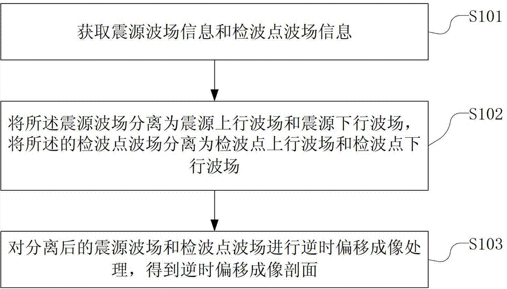
[0021] figure 1 is a flowchart of a reverse time migration imaging method provided by an embodiment of the present invention, such as figure 1 As shown, the reverse time migration imaging method includes the following steps:

[0022] S101. Acquiring source wave field information and receiver point wave field information.

[0023] In the embodiment of the present invention, step S101 may include the following sub-steps:

[0024] Obtain single shot data and perform pre-stack preprocessing on single shot data;

[0025] The forward wave field extrapolation and reverse time extrapolation of the single shot data output by the pre-stack preprocessing are used to obtain the source wave field information and receiver point wave field information at each time step.

[0026] Specifically, single-shot data collected by seismic data can be loaded; pre-stack preprocessing such as static correction and denoising can be performed on the loaded single-shot data in order to obtain single-sho...

Embodiment 2

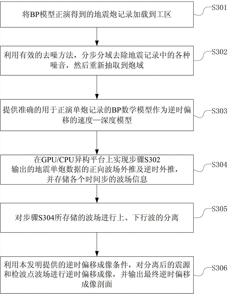
[0057] In order to test the accuracy and stability of the present invention, this embodiment tests the most typical BP (British Petroleum, British Petroleum) mathematical model in the field of geophysics. image 3 is a flow chart of a reverse time migration imaging method provided in this embodiment, such as image 3 As shown, the reverse time migration imaging method includes the following steps:

[0058] S301, loading the seismic shot records obtained by the forward modeling of the BP model into the work area.

[0059] S302, using an effective denoising method to remove various noises in the seismic records step by step and domain by domain, and then re-extract to the shot domain.

[0060] S303, providing an accurate BP mathematical model for forward single-shot recording as a velocity-depth model of reverse time migration.

[0061] S304. Realize forward wave field extrapolation and reverse time extrapolation of the seismic single-shot data output in step S302 on a GPU / CPU...

Embodiment 3

[0068] Figure 4 It is a module diagram of a reverse time migration imaging device provided by an embodiment of the present invention. The reverse time migration imaging device uses the method described in Embodiment 1 to generate a reverse time migration imaging section, as shown in Figure 4 As shown, the reverse time migration imaging device includes:

[0069] The wave field information acquiring unit 401 is configured to acquire the wave field information of the seismic source and the wave field information of the receiver point.

[0070] In the embodiment of the present invention, the wave field information acquisition unit 401 may also include:

[0071] The preprocessing module is used to obtain single-shot data and perform pre-stack preprocessing on single-shot data;

[0072] The extrapolation processing module is used for forward wave field extrapolation and reverse time extrapolation of single shot data output by pre-stack preprocessing, and obtains source wave fiel...


PUM


Abstract

The invention relates to a reverse time migration imaging method and a device. The reverse time migration imaging method comprises the steps of obtaining focus wave field information and detection point wave field information, detaching a focus wave field into a focus upper wave field and a focus lower wave field and detaching a detection point wave field into a detection point upper wave field and a detection point lower wave field according to the obtained focus wave field information and the obtained detection point wave field information, carrying out reverse time migration imaging process on the focus wave field and the detection point wave field which are detached, and then a reverse time migration imaging section is obtained. According to the reverse time migration imaging method and the device, low frequency noise produced in a reverse time migration process is eliminated, amplitude preservation performance is high, and good parallel characteristics of interior wave field calculation are maintained. The reverse time migration imaging method and the device are especially suitable for being used on a central processing unit (CPU) of a graphics processor or on a CPU heterogeneous platform. Calculating efficiency of reverse time migration is greatly improved.

Description

technical field [0001] The present invention relates to the technical field of geophysical exploration seismic data processing, in particular to the technical field of oil and gas exploration seismic data processing, and in particular to a reverse time migration imaging method and device. Background technique [0002] With the continuous development of oil and gas exploration technology, the target of oil and gas exploration has gradually shifted to the "double complex" area with complex surface conditions and complex underground geological structures, and the traditional imaging method has been unable to meet the imaging of "double complex" area. At present, the depth migration imaging methods used in large-scale industrial applications in China are mainly the Kirchhoff integral method based on ray theory and the ray beam migration method, but these methods are approximate solutions to the wave equation, and they cannot image well for high and steep dip angles. , and comple...

Claims


Application Information

Patent Timeline
Patent Type & Authority Applications(China)
IPC IPC(8): G01V1/28G01V1/36
Inventor 王宇超胡自多徐兴荣刘文卿吕彬韩令贺杨哲赵伟王述江
Owner PETROCHINA CO LTD
Why Eureka
Try Eureka