Wide view field logarithm pole coordinating mapping imaging method based on curve surface lens array

A log polar coordinate, curved lens technology, applied in lens, optics, instruments, etc., can solve the problem of difficult to achieve large field of view imaging, and achieve the effect of realizing large field of view imaging, expanding field of view, and improving quantum efficiency

Inactive Publication Date: 2013-05-08
BEIJING INSTITUTE OF TECHNOLOGYGY
View PDF3 Cites 9 Cited by
  • Summary
  • Abstract
  • Description
  • Claims
  • Application Information

AI Technical Summary

Problems solved by technology

[0004] The purpose of the present invention is to solve the problem that it is difficult to realize large field of view imaging in the prior art. The present invention proposes a wide field of view logarithmic polar coordinate mapping imaging method based on a curved lens array

Method used


Image

  • Wide view field logarithm pole coordinating mapping imaging method based on curve surface lens array
  • Wide view field logarithm pole coordinating mapping imaging method based on curve surface lens array
  • Wide view field logarithm pole coordinating mapping imaging method based on curve surface lens array

Examples


Embodiment 1

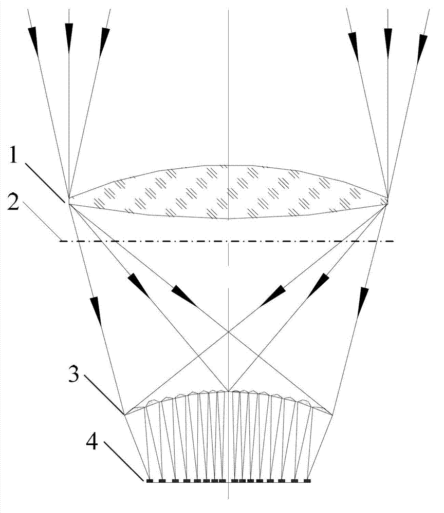
[0042] A wide field of view logarithmic polar coordinate mapping imaging method based on a curved lens array, which consists of a front optical system, a curved non-uniform lens array and a photoelectric detection array in order from top to bottom, such as figure 1 shown.

[0043] The front optical system is a converging system, which mainly converges the incident light.

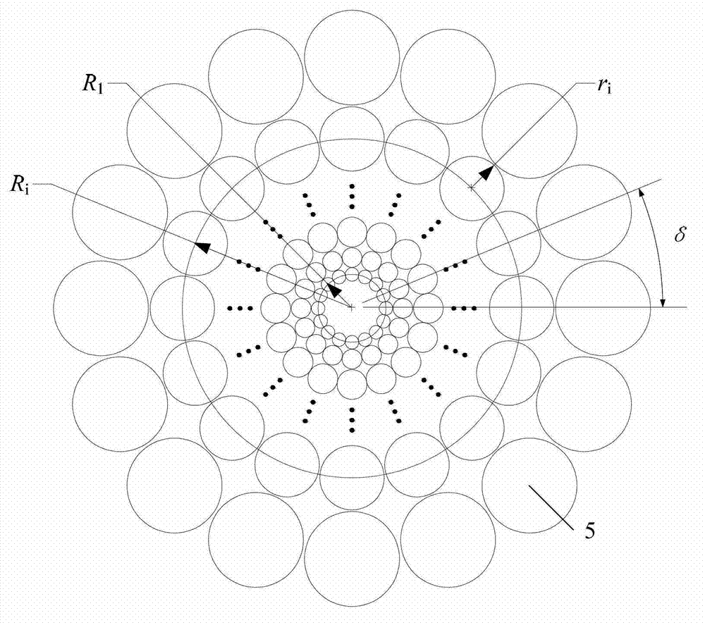
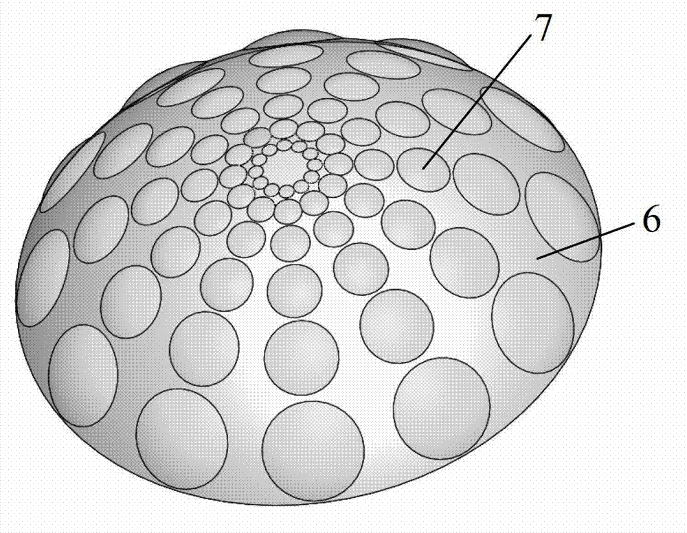
[0044] The curved non-uniform lens array is composed of non-uniform optical lenses distributed according to the curved surface, such as image 3 Shown: With the vertex of the curved surface as the center, M (M>2) rings of optical lenses are set, and N (N>3) optical lenses are uniformly arranged in each ring, and the centers of N optical lenses are evenly distributed in the ring. In the same ring, the apertures and other optical parameters of the N optical lenses are the same; the settings of the apertures and other optical parameters of the optical lenses in adjacent rings meet the requirements of logarithm...


PUM


Abstract

The invention relates to a wide view field logarithm pole coordinating mapping imaging method based on a curve surface lens array and belongs to the technical field of photoelectric imaging sensors. The wide view field logarithm pole coordinating mapping imaging method based on the curve surface lens array is sequentially composed of a fronting optical system, a curve surface non-uniform lens array and a photoelectric detection array from top to sown. According to the wide view field logarithm pole coordinating mapping imaging method based on the curve surface lens array, the curve surface optical lens array is used, so that the view field of an imaging system is enlarged, large view field imaging can be achieved, and the sensitivity of a logarithm pole coordinating mapping sensor is improved.

Description

technical field [0001] The invention relates to a wide field of view logarithmic polar coordinate mapping imaging method based on a curved lens array, and belongs to the technical field of photoelectric image sensors. Background technique [0002] The logarithmic polar coordinate mapping imaging technology simulates the non-uniform sampling mechanism of the human retina, which can reduce information redundancy. At the same time, based on this technology, the scale and rotation invariance of the target can be obtained, thereby eliminating the influence of target scale and rotation changes, thereby improving the speed and accuracy of the photoelectric detection system for detecting and tracking moving targets. Therefore, logarithmic polar coordinate mapping imaging technology has broad application prospects in aviation, aerospace, robotics, intelligent monitoring and other fields. [0003] At present, the existing logarithmic polar coordinate mapping imaging method is mainly ...

Claims


Application Information

Patent Timeline
Patent Type & Authority Applications(China)
IPC IPC(8): G02B3/06G02B3/00G02B27/00
Inventor 郝群宋勇樊凡曹杰刘韬
Owner BEIJING INSTITUTE OF TECHNOLOGYGY
Why Eureka
Try Eureka