
Exposure alignment method for glass substrate

A technology of glass substrate and exposure area, which is applied in the field of exposure and alignment of glass substrates, and can solve the problems that alignment marks cannot be produced, graphics shift, and alignment accuracy is difficult to ensure.

Active Publication Date: 2013-05-08
TCL CHINA STAR OPTOELECTRONICS TECH CO LTD
View PDF5 Cites 21 Cited by
  • Summary
  • Abstract
  • Description
  • Claims
  • Application Information

AI Technical Summary

Problems solved by technology

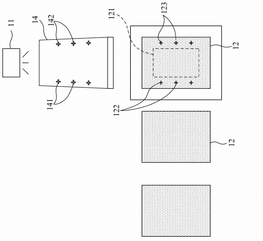
[0004] However, to perform exposure on a single large-size glass substrate, it is necessary to divide the pattern of the photomask into multiple pieces, and to perform multiple exposure splicing on a single large-size glass substrate to form a large-size exposure pattern, and then on a single large-size glass substrate. The overlapping splicing exposure area of ​​the photomask is generated on the substrate. Since the splicing exposure area is a display area on a single large-size glass substrate, the alignment mark can only be generated on the single large-size glass substrate. On the left and right sides of the periphery of the area, alignment marks cannot be generated in the splicing exposure area (display area), so that the splicing exposure area of ​​the single large-size glass substrate cannot be realized by alignment marks in the exposure of the last few layers and the exposure of the first layer. Automatic alignment, so it is difficult to ensure the alignment accuracy of the last few layers of exposure in the spliced ​​exposure area and the first layer of exposure, resulting in a graphic offset between the last few layers of exposure in the spliced ​​exposure area and the first layer of exposure

Method used


Image

  • Exposure alignment method for glass substrate
  • Exposure alignment method for glass substrate
  • Exposure alignment method for glass substrate

Examples


Embodiment Construction

[0021] The following descriptions of the various embodiments refer to the accompanying drawings to illustrate specific embodiments in which the present invention can be practiced. Furthermore, the directional terms mentioned in the present invention, such as "upper", "lower", "top", "bottom", "front", "back", "left", "right", "inside", " Outer, Side, Surround, Center, Horizontal, Horizontal, Vertical, Longitudinal, Axial, Radial, Topmost, or Bottommost etc. are merely for reference to the directions of the attached drawings. Therefore, the directional terms used are used to illustrate and understand the present invention, but not to limit the present invention. In addition, in order to make the above-mentioned purposes, features and advantages of the present invention more obvious and understandable, the preferred embodiments of the present invention are specifically cited below, together with the accompanying drawings, as follows:

[0022] Please refer to figure 2 , 3 As...


PUM


Abstract

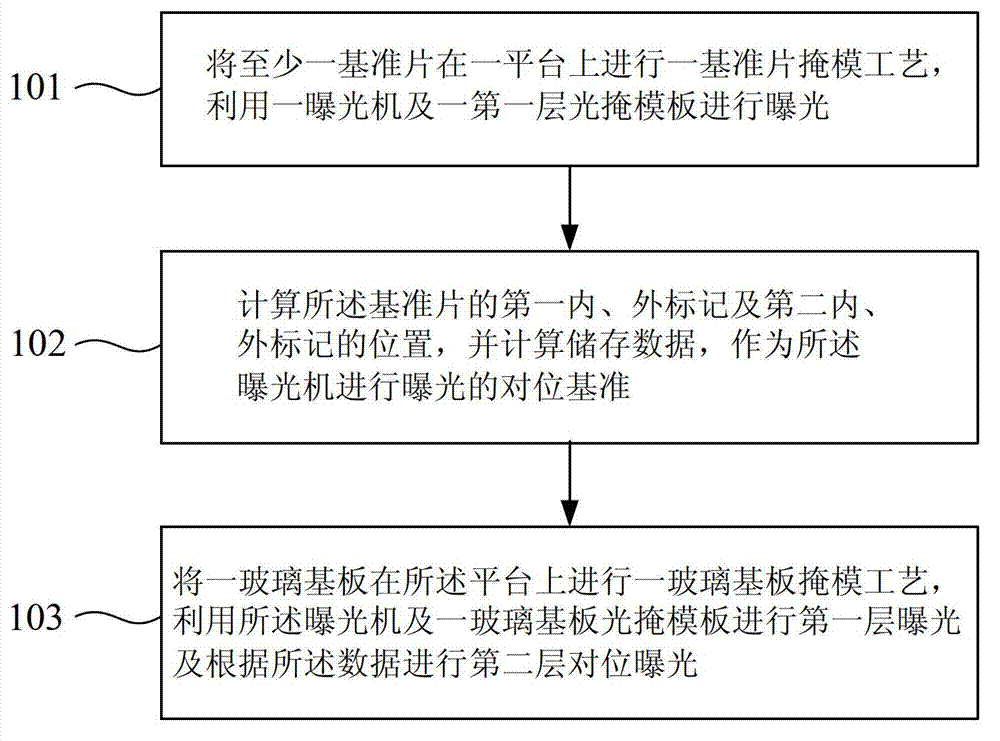
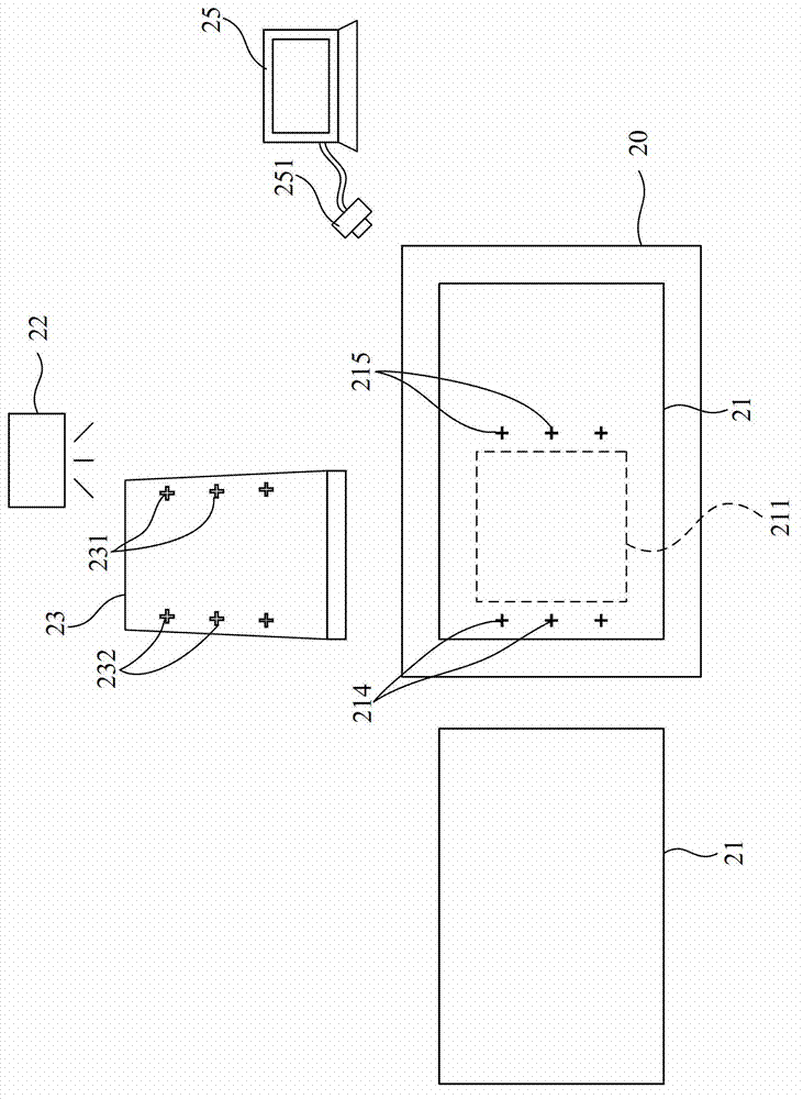
The invention discloses an exposure alignment method for a glass substrate. The method comprises the following steps of: treating a reference piece by using a reference piece masking technology, and exposing the treated reference piece by an exposure machine and a first layer of optical mask plate; calculating the positions of a first inner mark, a first external mark, a second inner mark and a second external mark of the reference piece, and storing calculated data as the alignment references for exposure; and treating one glass substrate by using the glass substrate masking technology, and exposing by the exposure machine and one glass substrate optical mask plate, and projecting at least two layers of exposure regions, and at least one splicing region on the glass substrate, wherein the splicing region is subjected to alignment exposure according to the data. The data of the first inner mark, the first external mark, the second inner mark and the second external mark which are formed by the reference piece during the exposing are calculated and stored, and thus, the splicing region exposed by the glass substrate can take the data as the alignment references, the pattern alignment accuracy in the exposure of the glass substrate is guarantee, and the offset of exposed patterns of the glass substrate can be avoided.

Description

【Technical field】 [0001] The invention relates to an exposure alignment method, in particular to an exposure alignment method for a glass substrate. 【Background technique】 [0002] In the production of large-size thin film transistor (Thin Film Transistor, TFT) array substrates of liquid crystal displays (Liquid Crystal Display, LCD), the exposure process will encounter a single large-size glass substrate pattern than the photomask (Photo Mask). In the case of larger graphics, in this case, it is necessary to divide the graphics on the photomask into multiple pieces on a single large-size glass substrate for multiple exposures, and use multiple photomask patterns to splice on a single large-size glass substrate graphics. [0003] see figure 1 As shown, in the thin film transistor (TFT) array substrate exposure process, an exposure machine 11 and a photomask 14 are used to expose a glass substrate 12, and the first layer of the glass substrate 12 is exposed in an exposure a...

Claims


Application Information

Patent Timeline
Patent Type & Authority Applications(China)
IPC IPC(8): G03F7/20G03F9/00
Inventor 付延峰
Owner TCL CHINA STAR OPTOELECTRONICS TECH CO LTD
Learn More