Lens antenna based on metamaterial

A technology of lens antennas and metamaterials, applied in antennas, electrical components, etc., can solve problems affecting antenna performance and achieve the effect of reducing reflection and increasing incident efficiency

Active Publication Date: 2013-05-08
KUANG CHI INST OF ADVANCED TECH +1
View PDF4 Cites 6 Cited by
  • Summary
  • Abstract
  • Description
  • Claims
  • Application Information

AI Technical Summary

Problems solved by technology

[0004] The purpose of the present invention is to overcome the defect that the performance of the lens antenna will be seriously affected by reducing the size of the lens in the prior art, and to provide a lens antenna based on metamaterials. The antenna adopts metamaterial technology and can be applied in a narrow space without affecting the antenna. performance

Method used


Image

  • Lens antenna based on metamaterial
  • Lens antenna based on metamaterial
  • Lens antenna based on metamaterial

Examples


Embodiment Construction

[0027] The present invention will be described in further detail below in conjunction with the embodiments and the accompanying drawings, but the embodiments of the present invention are not limited thereto.

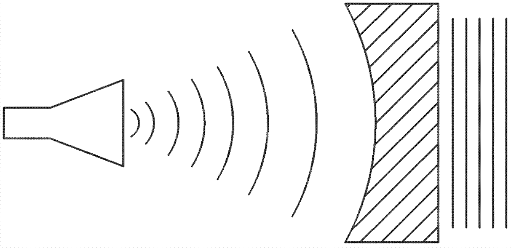
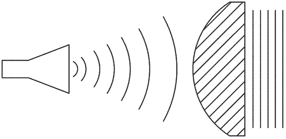
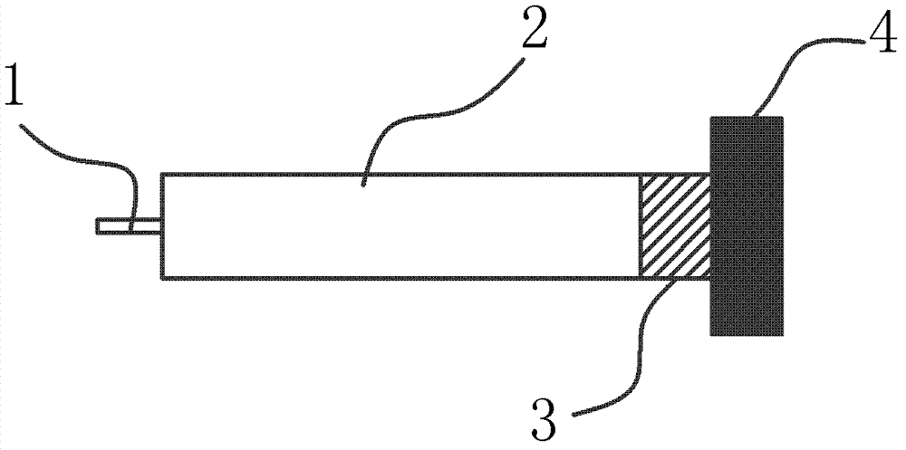
[0028] Such as figure 2 Shown is a schematic structural view of the lens antenna based on metamaterials in the present invention, the lens antenna includes: a feed 1, a waveguide 2, a metamaterial impedance converter 3 and a metamaterial lens 4, the feed 1, waveguide 2. The metamaterial impedance converter 3 and the metamaterial lens 4 are connected in sequence. The feed source 1 is connected to the waveguide 2 through a peripheral feeder line (not shown in the figure), and electromagnetic waves are formed in the waveguide 2 to enter the metamaterial impedance transformer 3, and finally converge and radiate through the metamaterial lens 4, in order to make the metamaterial The material impedance converter 3 transforms the electromagnetic wave reflected from the surface ...


PUM


Abstract

The invention relates to the filed of wireless communication and provides a lens antenna based on metamaterial. The lens antenna comprises a feed source, a waveguide, a metamaterial impedance transformer and a metamaterial lens. The feed source, the waveguide, the metamaterial impedance transformer and the metamaterial lens are sequentially connected. The metamaterial lens comprises a plurality of metamaterial lamellas with the same refractive index distribution, refractive indexes of the metamaterial lamellas are distributed in a circle shape with the center as the center of the circle, the refractive indexes are gradually decreased along with increase of the radius, and the refractive indexes at the position where the radius is the same are the same. According to the lens antenna based on the metamaterial, by adjusting distribution rules of dielectric constants and magnetic conductivities inside the metamaterial, the refractive indexes in the metamaterial can be exited in a paralleled mode through magnetic wave signals in the metamaterial, and therefore the lens antenna is good in directivity and large in benefit.

Description

technical field [0001] The invention relates to the field of wireless communication, in particular to a lens antenna based on metamaterials. Background technique [0002] Existing lens antennas mainly realize electromagnetic space beam modulation through dielectric lenses. According to the different mechanism of the lens medium, they can be divided into accelerating lenses as shown in Figure 1(a) and delaying lenses as shown in Figure 1(b). Among them, the accelerated lens is mainly realized by the E-plane metal slab waveguide. Retardation lenses are mainly realized by H-surface metal plates and non-metallic dielectrics, such as synthetic resin, polystyrene and polytetrafluoroethylene. The modulation of the waveform is mainly realized by changing the lens material and thickness. [0003] In some specific occasions, due to the special conditions of specific application scenarios, the size of the lens antenna is strictly limited, but because reducing the size of the lens wil...

Claims


Application Information

Patent Timeline
Patent Type & Authority Applications(China)
IPC IPC(8): H01Q19/06H01Q15/02H01Q13/00
Inventor 刘若鹏季春霖岳玉涛殷俊
Owner KUANG CHI INST OF ADVANCED TECH
Why Eureka
Try Eureka