Microalgae growth pond design

A microalgae and slender technology, applied in biochemical equipment and methods, enzymology/microbiology devices, biochemical instruments, etc., can solve problems such as uneven depth of breeding areas and productivity defects

Inactive Publication Date: 2013-05-08
GENERAL ATOMICS
View PDF13 Cites 6 Cited by
  • Summary
  • Abstract
  • Description
  • Claims
  • Application Information

AI Technical Summary

Problems solved by technology

At this point, the larger the area, the more uneven the depth across the cultured area, which can be a productivity deficit

Method used


Image

  • Microalgae growth pond design
  • Microalgae growth pond design
  • Microalgae growth pond design

Examples


Embodiment Construction

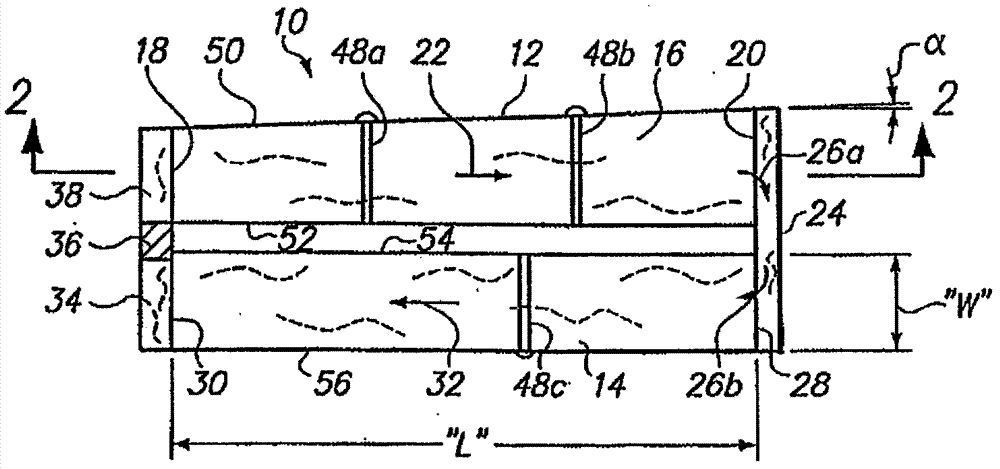
[0018] first reference figure 1 , figure 1 A raceway pool according to the invention is shown and generally designated 10 . Specifically, in figure 1 It can be seen that the pool 10 includes a first channel 12 and a second channel 14, which are shown alongside each other in side-by-side relationship. Furthermore, channels 12 and 14 are shown in fluid communication with each other, with fluid medium 16 flowing continuously from one channel to the other. Those skilled in the art should understand that, figure 1 The arrangement of channels 12 and 14 shown in is exemplary only. Channels 12 and 14 can have any of different arrangements depending on the topographical characteristics of the zone in which pool 10 is used and the ability to meet other requirements of the invention.

[0019] In more detail, figure 1 Fluid medium 16 is shown flowing in first channel 12 from upstream end 18 to downstream end 20 , as indicated by arrow 22 . After flowing through first channel 12, fl...


PUM

PropertyMeasurementUnit
lengthaaaaaaaaaa

Abstract

A raceway pond for circulating microalgae in a fluid medium includes a plurality of interconnected channels. Each channel is straight and has a structured gradient, due to tilt or terracing, that moves the fluid medium along the raceway. In operation, the concentration of microalgae in the fluid medium is maintained substantially constant, and the depth of the fluid medium in the raceway is maintained below a pre-determined level.

Description

technical field [0001] The present invention relates to plug flow reactors (PFRs) having circulating raceway ponds for growing microalgae in a fluid medium. More specifically, the present invention relates to a plug flow reactor that provides conditions for the production of microalgae with an oil content of up to 60%. The present invention is particularly useful, but not limited to, plug flow reactors that rely on gravity to move microalgae in fluid media along the length of the plug flow reactor's raceway. Background technique [0002] The growth rate of microalgae in a liquid environment depends on several completely different factors. First, it is well known that the fluid medium (ie, the liquid environment) in which microalgae grow must be circulated to provide mixing of the microalgae and to expose the microalgae to light for photosynthesis. Second, each algae species has an optimal concentration to consume all or nearly all of the available resources in the fluid me...

Claims


Application Information

Patent Timeline
Patent Type & Authority Applications(China)
IPC IPC(8): A01G7/00C12M3/00C12M1/00
CPCC12M21/02C12M23/18C12M27/18C12M23/02
Inventor 大卫·A·哈茨勒贝克
Owner GENERAL ATOMICS
Why Eureka
Try Eureka