Sawing apparatus and process for producing a scintillator structured into scintillator elements and scintillator having scintillator elements

A technology of scintillator and sawing device, which is applied in the direction of manufacturing tools, fine working devices, radiation intensity measurement, etc., can solve the problems of high cost and time-consuming, and achieve the goals of improving heat discharge, good sawing tolerance, and reducing processing time Effect

Inactive Publication Date: 2013-05-08
SIEMENS AG
View PDF5 Cites 0 Cited by
  • Summary
  • Abstract
  • Description
  • Claims
  • Application Information

AI Technical Summary

Problems solved by technology

Therefore, sawing out the gap is extremely time-consuming and thus also cost-intensive

Method used


Image

  • Sawing apparatus and process for producing a scintillator structured into scintillator elements and scintillator having scintillator elements
  • Sawing apparatus and process for producing a scintillator structured into scintillator elements and scintillator having scintillator elements
  • Sawing apparatus and process for producing a scintillator structured into scintillator elements and scintillator having scintillator elements

Examples


Embodiment Construction

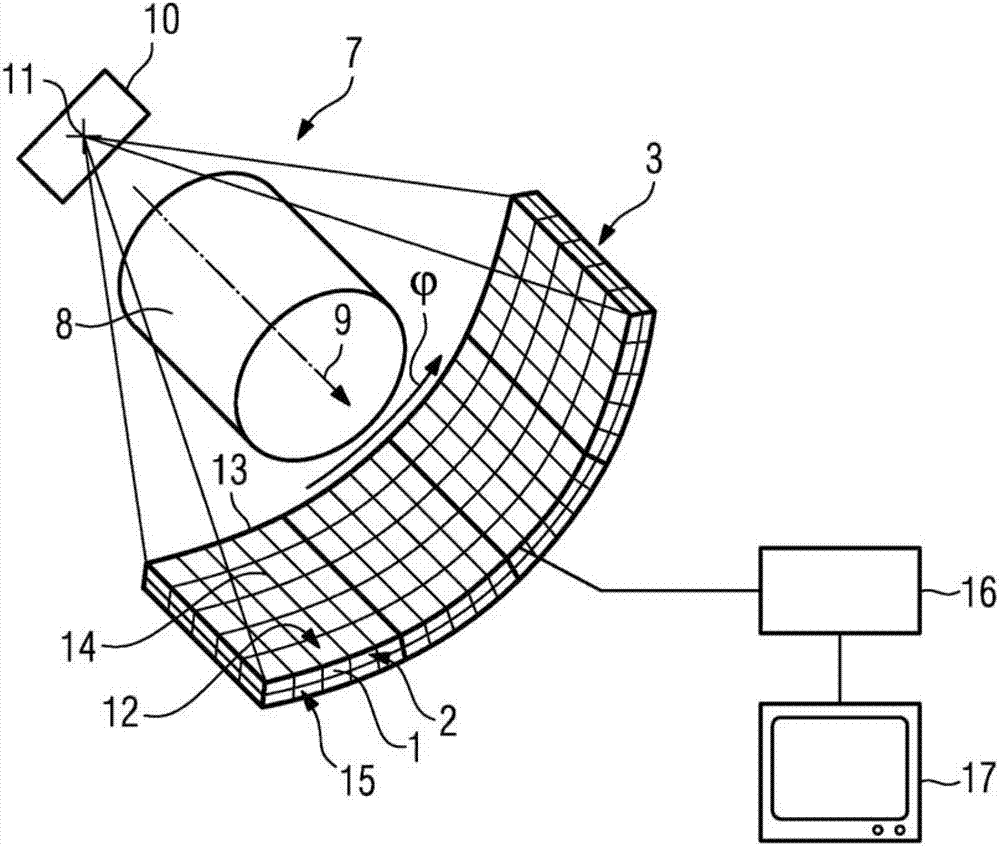
[0029] exist figure 1 The computed tomography system 7 is shown partly in perspective and partly in block diagram form. The computed tomography system 7 includes a patient table (not shown) for placing a patient 8 to be examined. Furthermore, a gantry (not shown) is included, which has the imaging system 10 , 3 mounted rotatably about the system axis 9 . The imaging system 10 , 3 has an x-ray tube 10 and a radiation detector 3 arranged opposite it, so that during operation x-rays emanating from a focal point 11 of the x-ray tube 10 pass through the patient 8 and reach the radiation detector 3 . The radiation detector 3 for the spatially resolved detection of x-ray radiation is divided into pixels 12, wherein groups of pixels are respectively located in The radiation detector modules 13 are formed in rows according to the lines marked in bold.

[0030] To convert the x-ray radiation into optically visible light, the radiation detector 3 has a scintillator 2 which is divided...


PUM

PropertyMeasurementUnit
widthaaaaaaaaaa

Abstract

The invention relates to a sawing apparatus (4) for producing a scintillator (2), which is structured into scintillator elements (1), for a radiation detector (3). Said sawing apparatus further comprises a rotatably mounted saw blade (5) and an oscillating means (6) for kinematically subjecting the saw blade to oscillation in the ultrasound frequency range. Through the additional oscillation of the saw blade (5), it is possible to achieve better cooling of the saw blade (5) and better removal of sawing waste. This affords the advantage of higher achievable feed rates and longer durability of the saw blade (5). In addition, deep cuts can be made in the scintillator material in a single cutting process, with reduced edge fragmentation and therefore with little scrap. The invention also relates to such a process for producing the scintillator (2) structured into scintillator elements (1), and to a correspondingly structured scintillator (2).

Description

technical field [0001] The invention relates to a saw device and a method for producing a scintillator structured with scintillator elements and a scintillator structured with scintillator elements. Background technique [0002] Radiation detectors used in computed tomography systems are used to convert x-ray radiation into electrical signals which form the starting point for image reconstruction. So-called indirect conversion radiation detectors are currently used. Here, the conversion of the x-ray radiation takes place in two stages. In the first stage, the x-ray radiation is absorbed by means of a scintillator and converted into optically visible light pulses. The light pulses are then converted into electrical signals in the second stage by an array of photodiodes optically coupled to the scintillator. [0003] In order to achieve a certain spatial resolution, the scintillator is structured pixel-wise with individual scintillator elements. A scintillator ceramic such...

Claims


Application Information

Patent Timeline
Patent Type & Authority Applications(China)
IPC IPC(8): B28D5/02
CPCG01T1/20B28D5/022
Inventor M.米斯S.沃思
Owner SIEMENS AG
Why Eureka
Try Eureka