
High-accuracy respiratory monitor

A respiratory monitoring, high-precision technology, applied in the evaluation of respiratory organs, etc.

Inactive Publication Date: 2013-05-15
中国人民解放军第三0七医院
View PDF4 Cites 6 Cited by
  • Summary
  • Abstract
  • Description
  • Claims
  • Application Information

AI Technical Summary

Problems solved by technology

Therefore, the error measured by this method is mm level, which is not suitable for occasions that require relatively high precision.

Method used


Image

  • High-accuracy respiratory monitor
  • High-accuracy respiratory monitor
  • High-accuracy respiratory monitor

Examples


Embodiment Construction

[0021] The present invention will be further described in detail below in conjunction with the accompanying drawings.

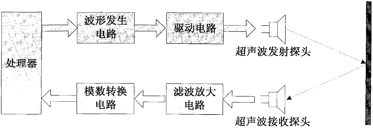
[0022] A high-precision respiration monitor uses high-precision ultrasonic ranging technology to display the patient's respiratory phase in real time on a computer screen. It is characterized in that the specific steps of the high-precision ultrasonic ranging technology are as follows:

[0023] Step 1: The processor generates an AC signal of a certain frequency by controlling the waveform generating circuit. After the AC signal is amplified by the drive circuit and impedance matched, it drives the ultrasonic transmitting probe to emit a section of ultrasonic waves. The start time of ultrasonic emission is T0;

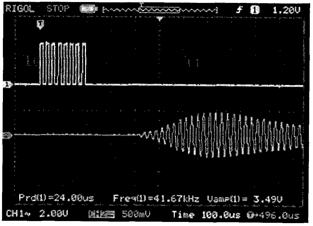
[0024] Step 2: Use a reverse-phase echo location method to accurately determine the starting time of the ultrasonic echo. After transmitting a cycle of ultrasonic waves, immediately transmit a reverse-phase ultrasonic wave. After superimposition, there ...


PUM


Abstract

Provided is a high-accuracy respiratory monitor. A processor controls a wave generation circuit to generate alternating current signals with a certain frequency. After amplifying of a drive circuit and impedance matching, the alternating current signals drive an ultrasonic wave transmitting probe to transmit a length of ultrasonic wave. The time when the ultrasonic wave is transmitted is T0. The starting time of echo of the ultrasonic wave is determined by using a reversed-phase echolocation method. The time interval between the time when the ultrasonic wave receiving probe receives the signals and the time when the ultrasonic wave transmitting probe transmits the ultrasonic wave is t. Time offset delta t is measured according to experience. At present, the distance can be calculated through the following formula: L= (Tr-T0-delta t)*v / 2, wherein delta t is a fixed value and can be measured according to experience, and V is sound velocity.

Description

technical field [0001] The invention belongs to the technical field of ultrasonic ranging, in particular to a high-precision ultrasonic ranging method. Background technique [0002] When performing radiotherapy for lung tumors, respiratory motion has always been an important consideration in target volume delineation, and it is important to measure the range of motion of the lesion. We ask the patient to hold his breath at the two phases of end-expiration and end-inspiration. At this time, two CT scans are performed, and the three-dimensional coordinate data difference of the lung lesion in the two CTs is measured, and the movement of the lesion can be obtained. scope. However, in actual work, it is found that only the staff verbally requires the patient to hold his breath, which cannot ensure that the patient's actual breathing phase is consistent with the required breathing phase. We added a CT scan during free breathing. Theoretically, the lesion position at this time s...

Claims


Application Information

Patent Timeline
Patent Type & Authority Applications(China)
IPC IPC(8): A61B5/08
Inventor 申戈邢旭东李功杰周振山张鹏盛洪国张洪涛刘海豹
Owner 中国人民解放军第三0七医院
Learn More