Spray head frame of printer

A nozzle frame and printer technology, applied in printing, transfer materials, power transmission devices, etc., can solve problems such as large assembly errors, low adjustment efficiency and precision, and difficult to guarantee the dimensional accuracy of spare parts

Active Publication Date: 2013-05-15
WENZHOU ACPASS DISPLAY EQUIP
View PDF6 Cites 3 Cited by
  • Summary
  • Abstract
  • Description
  • Claims
  • Application Information

AI Technical Summary

Problems solved by technology

[0003] Please refer to image 3 , image 3 It is a schematic diagram of the structure of the printer nozzle holder in the prior art. The spare parts of the printer nozzle holder generally include the nozzle slide plate 108, the nozzle holder 104, the height adjustment device of the nozzle holder, the ink bag pressing piece 111, the nozzle adjustment plate 101 and the nozzle adjustment plate level Adjusting devices, etc., are currently manufactured by machining. It is difficult to guarantee the dimensional accuracy of machined parts, and their dimensional consistency is relatively low. It is also difficult to guarantee each dimensional tolerance and shape tolerance of machined parts. The error is large, and there are many adjustment steps after assembly, and the adjustment efficiency and accuracy are low.

Method used


Image

  • Spray head frame of printer
  • Spray head frame of printer
  • Spray head frame of printer

Examples


Embodiment Construction

[0024] The core of the present invention is to provide a printer nozzle frame to improve the assembly accuracy of its parts.

[0025] In order to enable those skilled in the art to better understand the solution of the present invention, the present invention will be further described in detail below with reference to the accompanying drawings and specific embodiments.

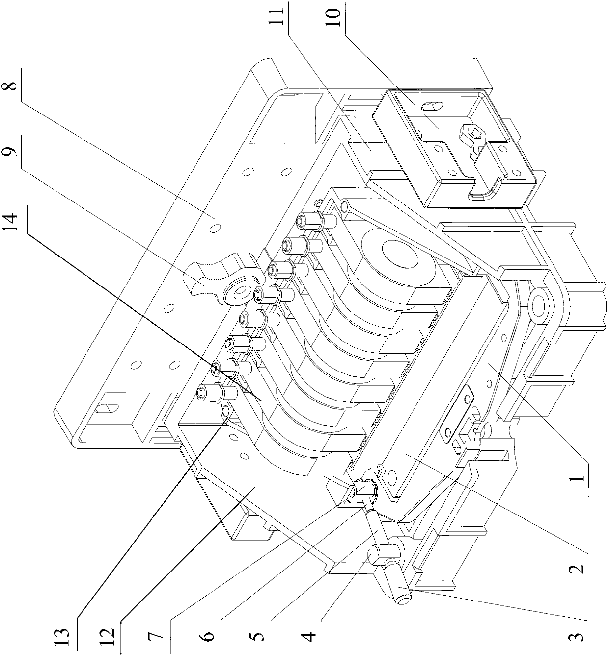
[0026] Please refer to figure 1 , figure 1 It is a schematic structural diagram of the first specific embodiment of the printer nozzle holder provided by the embodiment of the present invention.

[0027] The printer nozzle holder provided by the embodiment of the present invention includes a nozzle slide 8, a nozzle holder 12, a nozzle holder height adjustment device, an ink bag press 13, a nozzle adjustment plate 1 and a nozzle adjustment plate level adjustment device, wherein the nozzle holder 12 can It is slidable up and down on the nozzle slide 8. The nozzle holder height adjustment device is used to adjust the...


PUM


Abstract

The invention discloses a spray head frame of a printer. The spray head frame comprises a spray head sliding plate, a spray head frame body, a spray head frame height adjusting device, an ink bag pressing piece, a spray head adjusting plate and a spray head adjusting plate horizontal adjusting device, wherein the spray head frame body is arranged on the spray head sliding plate in a vertical sliding mode, the spray head frame height adjusting device is used for adjusting the height of the spray head frame body, the spray head adjusting plate is used for driving a spray head of the spray head frame of the printer to be parallel to the spray head sliding plate, the spray head adjusting plate is arranged on the spray head frame body in a horizontal sliding mode, the spray head adjusting plate horizontal adjusting device is used for adjusting the horizontal position of the spray head adjusting plate, the ink bag pressing piece is used for fixing an ink bag of the spray head frame of the printer, and the spray head sliding plate, the spray head frame body, the spray head frame height adjusting device, the ink bag pressing piece, the spray head adjusting plate and the spray head adjusting plate horizontal adjusting device are molded in an injection mode or a die-casting mode. The parts of the spray head frame of the printer are molded in the injection mode or the die-casting mode so that dimensional accuracy and dimensional consistency of the parts are improved, and therefore assembly accuracy of the parts is improved.

Description

Technical field [0001] The invention relates to the technical field of printing devices, in particular to a printer nozzle holder. Background technique [0002] The printer is one of the output devices of the computer and is used to print the computer processing results on the relevant media. The printer is a complex and sophisticated mechanical and electronic device, and no matter what kind of printer, its structure can basically be divided into two parts: mechanical device and control circuit, these two parts are closely related. The printer nozzle frame belongs to the mechanical device. [0003] Please refer to image 3 , image 3 It is a schematic diagram of the structure of the printer nozzle holder in the prior art. At present, the parts of the printer nozzle holder generally include the nozzle slide 108, the nozzle holder 104, the height adjustment device of the nozzle holder, the ink bag press 111, the nozzle adjustment plate 101 and the nozzle adjustment plate level. Adjus...

Claims


Application Information

Patent Timeline
Patent Type & Authority Applications(China)
IPC IPC(8): B41J25/304
Inventor 薛征宇
Owner WENZHOU ACPASS DISPLAY EQUIP
Why Eureka
Try Eureka