Ground source heat pump tube embedment method based on piling process

A technology of ground source heat pump and pile planting, which is applied to geothermal energy, heating devices, geothermal energy power generation, etc., can solve the problems of weak heat exchange performance, affecting the bearing capacity of pipe piles, and troublesome construction, so as to achieve good heat exchange performance and reduce The risk of breakage and the effect of reducing construction costs

Active Publication Date: 2013-05-15
黄吉永
View PDF5 Cites 21 Cited by
  • Summary
  • Abstract
  • Description
  • Claims
  • Application Information

AI Technical Summary

Problems solved by technology

The ground source heat pump tubes using this embedding method are not in sufficient contact with the soil layer, and the heat exchange performance is weak; since the pile top must be embedded in the concrete foundation for a certain length, the ground source heat pump tube cannot cross the pile top and then bend to the bottom of the concrete foundation. Therefore, it is necessary to cut through the pipe pile wall to bend the ground source heat pump pipe into the soil layer at the bottom of the foundation. This will not only trouble the construction, but also damage the structure of the pipe pile top and affect the bearing capacity of the pipe pile.

Method used


Image

  • Ground source heat pump tube embedment method based on piling process

Examples


Embodiment 1

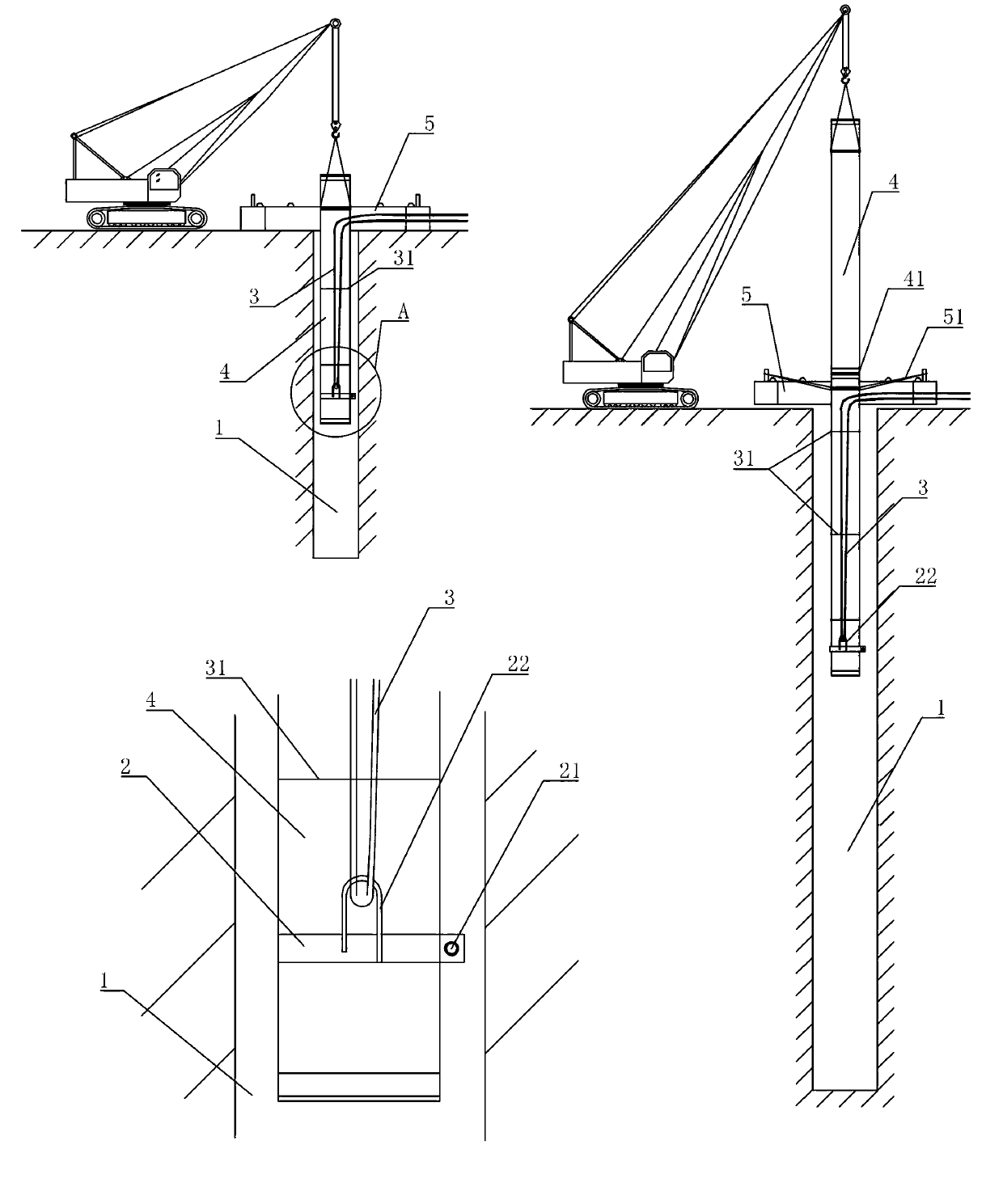
[0024] Embodiment 1: A ground source heat pump tube embedding method based on pile planting process, comprising the following steps:

[0025] 1): Use a special spiral drilling machine to drill into the soil to break the soil structure. After the soil is loosened, inject high-pressure water and use a special spiral drilling machine to stir the soil into mud. After the hole reaches the design depth Then inject the cement slurry and stir it with a special screw drilling machine, and after putting away the special screw drilling machine, a pile planting hole 1 is formed, and the inner diameter of the pile planting hole 1 is greater than the outer diameter of the pipe pile;

[0026] 2): Fix and install a steel ferrule around the outer surface of the pipe pile near the bottom. The steel ferrule is a ring-shaped steel plate 2, and the hook 22 is welded on the ring-shaped steel plate 2. The two ends of the ring-shaped steel plate 2 are screwed and fixed with bolts 21. The ring-shaped s...

Embodiment 2

[0034] Embodiment 2: The remaining parts are the same as Embodiment 1, the difference is that the joint joint 41 is a connection formed by mechanically fixing two adjacent unit pile sections 4 together.


PUM


Abstract

The invention discloses a ground source heat pump tube embedment method based on a piling process. The ground source heat pump tube embedment method based on the piling process is characterized by comprising steps as below: forming piling holes by using a piling machine, wherein the inner diameter of the piling holes is larger than the outer diameter of a tubular pile; installing at least one hook at the position near the bottom of the outer surface of the tubular pile, preparing ground source heat pump tubes according to a preset length and a preset amount, fixing the ground source heat pump tubes on the hook, and fixing the ground source heat pump tubes on the tubular wall of the tubular tubes; hanging the tubular piles right above the piling holes in a perpendicular mode; putting the tubular piles into the piling holes, utilizing self weights of the tubular piles to enable the tubular tubes to sink, burying the ground source heat pump tubes underground through the traction of the hook, wherein the part, buried underground, of the ground source heat pump tubes is low in breaking risks, low in disturbance of the piling process of the tubular tubes, and therefore a plurality of ground source heat pump tubes can be buried at the same time under the condition permitted by engineering design.

Description

technical field [0001] The invention relates to a ground source heat pump pipe embedding method, in particular to a ground source heat pump pipe embedding method based on a pile planting process. Background technique [0002] Ground source heat pump technology is a means of using deep constant temperature geothermal energy as an energy source, and it is necessary to embed ground source heat pump pipes deep into the foundation. So far, the commonly used construction methods for embedding ground source heat pump pipes can be classified into the following three categories: [0003] First, use a drilling rig to drill a hole in the deep soil layer of the foundation according to the designed depth and then insert the ground source heat pump pipe. The ground source heat pump pipe is a flexible pipe body with relatively light weight. The intubation construction process is affected by the buoyancy of mud or groundwater, so artificial intubation is generally used. However, it is diff...

Claims


Application Information

Patent Timeline
Patent Type & Authority Applications(China)
IPC IPC(8): E02D7/00F24J3/08
CPCY02E10/10F24T10/10F24T2010/53
Inventor 黄吉永郑荣跃黄楠
Owner 黄吉永
Why Eureka
Try Eureka