Buried sand high energy gas stress cracking method
A high-energy gas fracturing, oil and gas technology, applied in the development of fluids, earthwork drilling, wellbore/well components, etc., can solve problems such as rapid energy loss, achieve effective fracturing effect, improve fracturing effect, and simplify complexity. Effect
- Summary
- Abstract
- Description
- Claims
- Application Information
AI Technical Summary
Problems solved by technology
Method used
Image

Examples
Embodiment 1
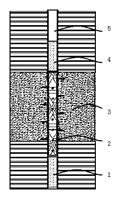
[0019] Embodiment 1: The application basic method of the present invention refers to figure 1 The upper and lower layers of the fracturing area (destination layer 3 ) are filled, and the high-energy gas fracturing device 2 is placed in the lower area of the filling covering layer 4 to detonate fracturing. The above basic methods can be applied in layers, that is, when there is a thinner interlayer for operation, the order from bottom to top is: bottom sand layer 1, high-energy gas fracturing device 2, compartment filling covering layer 4, high-energy gas fracturing The device 2 and the filling covering layer 4 are arranged in layers. After the upper layer is fractured by detonating, the casing is pressurized and conducts fracturing each layer step by step. After fracturing, sand washing operations are required to lift out the fracturing devices step by step to complete high-energy gas fracturing.
Embodiment 2
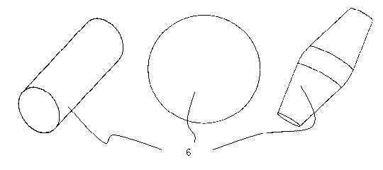
[0020] Embodiment 2: follow the basic method of embodiment 1 see figure 1 , when applied to single-layer fracturing, the steps are as follows: 1. Before the high-energy gas fracturing operation, the sand filling operation should be carried out to establish the bottom sand layer 1 to the vicinity of the target layer 3, and the height of the sand surface should be adjusted so that the distance from the target layer does not exceed 2 meters, and lower the liquid level as much as possible. 2. During fracturing construction, use a cable to attach a separate magnetic locator to detect the underlying sand surface, adjust the height of the sand surface, and increase the height of the sand surface by putting the above-mentioned filler 6 from the wellhead to make the height of the sand surface meet the requirements. Afterwards, the magnetic positioner is removed to lower the fracturing device 2 for generating high-energy gas to the destination layer 3 . The high-energy gas fracturing d...
Embodiment 3
[0021] Embodiment 3: It is basically the same as Embodiment 3, except that the high-energy gas fracturing device 2 can be replaced by a high-energy composite perforating device, which reduces the process but increases the operational risk. In addition, the method described in the present invention can be used in the construction of transforming formations using high-energy gas as power energy.
PUM
 Abstract
Description
Claims
Application Information
 - R&D
- Intellectual Property
- Life Sciences
- Materials
- Tech Scout
- Unparalleled Data Quality
- Higher Quality Content
- 60% Fewer Hallucinations
Browse by: Latest US Patents, China's latest patents, Technical Efficacy Thesaurus, Application Domain, Technology Topic, Popular Technical Reports.
© 2025 PatSnap. All rights reserved.Legal|Privacy policy|Modern Slavery Act Transparency Statement|Sitemap|About US| Contact US: help@patsnap.com