Direct measurement method of engine exhaust gas recirculation (EGR) rate and engine EGR valve

A technology of EGR valve and measurement method, applied in engine components, engine control, combustion engine, etc., can solve problems such as affecting the performance of the whole vehicle, reducing the aperture, and reducing the combustion performance of gasoline

Inactive Publication Date: 2013-05-15
CHERY AUTOMOBILE CO LTD
View PDF8 Cites 19 Cited by
  • Summary
  • Abstract
  • Description
  • Claims
  • Application Information

AI Technical Summary

Problems solved by technology

However, after the engine on the vehicle is used for a long time, a large amount of impurities will be deposited on the hole wall of the EGR valve, and the accumulation of impurities will inevitably lead to the reduction of the hole diameter, which will cause the actual exhaust gas volume of the engine on the vehicle to be less than Exhaust gas throughput in an ideal state, that is to say, the actual EGR rate is lower than the ideal EGR rate, which reduces gasoline combustion performance and affects vehicle performance

Method used


Image

  • Direct measurement method of engine exhaust gas recirculation (EGR) rate and engine EGR valve
  • Direct measurement method of engine exhaust gas recirculation (EGR) rate and engine EGR valve
  • Direct measurement method of engine exhaust gas recirculation (EGR) rate and engine EGR valve

Examples


Embodiment Construction

[0025] A method for directly measuring engine EGR rate, comprising the following steps:

[0026] a. Measure the fuel consumption meter and air-fuel ratio analyzer of the engine to obtain the fuel consumption of the engine B fuel and the excess air coefficient φ under the current working condition,

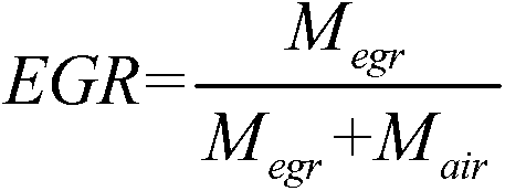
[0027] The mass flow M of the fresh air combusted in the engine cylinder is calculated according to the following relationship air :

[0028] m air =B fuel ×φ×14.5

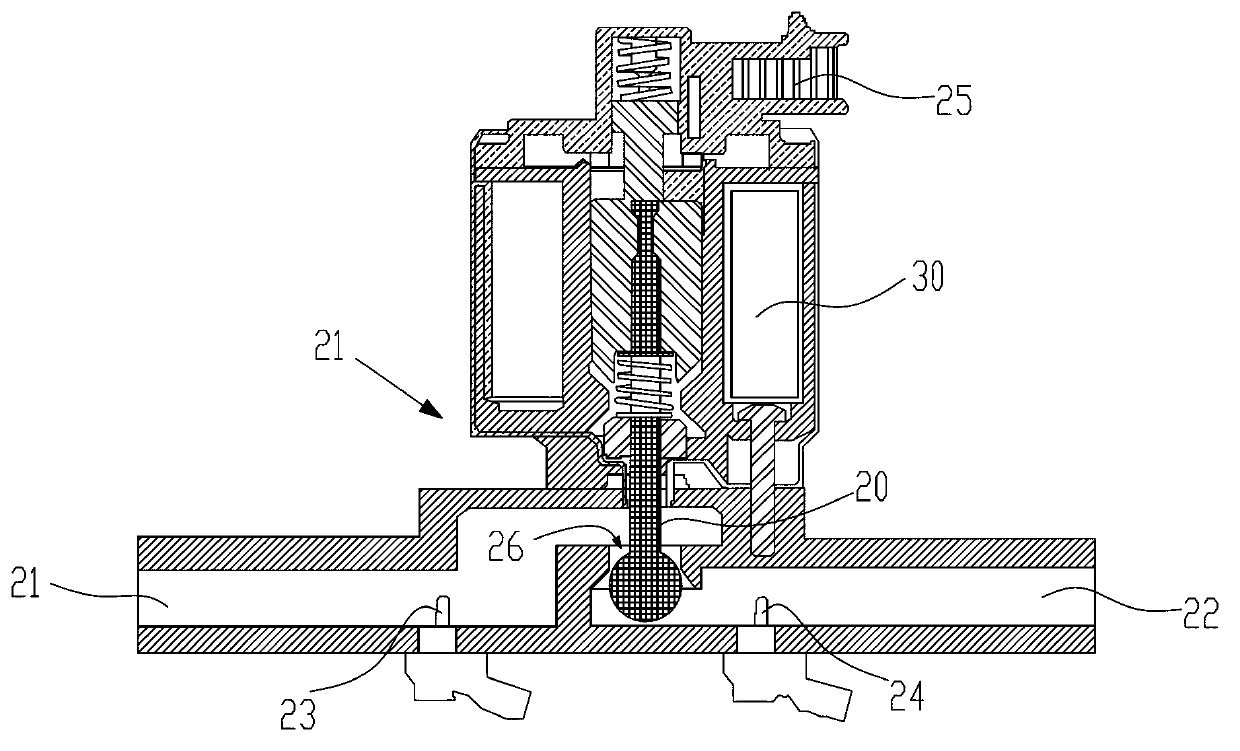
[0029] b. Measure the pressure and temperature P of the exhaust gas inlet of the EGR valve a , T a and the pressure and temperature P of the exhaust port of the EGR valve b , T b ;

[0030] c. Measure the cross-sectional area A of the exhaust passage of the EGR valve o ;

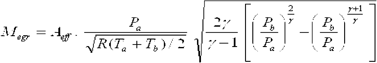
[0031] d. Calculate the exhaust gas mass flow rate M of the EGR valve according to the following relationship egr :

[0032] A eff =A o ×CFF

[0033] M egr = A ...


PUM


Abstract

The invention relates to the filed of engine exhaust emission recirculation rate measurement, in particular to a direct measurement method of engine exhaust gas recirculation (EGR) rate. The direct measurement method of engine exhaust gas recirculation (EGR) rate comprises the following steps: a. measuring a fuel consumption meter and an air-fuel ratio analysis meter of the engine to obtain fuel consumption Bfuel and an excess air coefficient phi under a current working condition, calculating and obtaining the mass flow rate Mair of refresh air burning in a cylinder of the engine through the following relation: Mair=Bfuel*phi*14.5, b. measuring the pressure Pa and the temperature Ta in an exhaust gas inlet of an EGR valve and the pressure Pb and the temperature Tb in an exhaust gas outlet of the EGR valve, c. measuring the section area of an exhaust duct of an EGR valve Ao, d. calculating and obtaining an exhaust gas mass flow rate Megr of the EGR valve according to the following relation: Aeff=Ao*CFF, wherein Aeff is the actual flow section area of the EGR valve, CFF is the theoretical flow coefficient of the EGR valve, R is gas constant and gamma is specific heat ratio, and e. calculating and obtaining the engine EGR rate through the following relation: EGR=Meger / (Megr plus Mair). According to the direct measurement method of EGR rate and engine EGR valve, the EGR rate is directly measured and obtained according to the temperature and the pressure of the exhaust gas inlet and the exhaust gas outlet of the EGR valve, measurement results are precise and reflect the engine EGR rate intuitively.

Description

technical field [0001] The invention relates to the field of measuring the exhaust gas recirculation rate of an engine, in particular to a method for directly measuring the EGR rate of an engine. Background technique [0002] Exhaust Gas Recirculation (Exhaust Gas Recirculation) is a technology (method or method) in which a small internal combustion engine for automobiles separates a part of the exhaust gas after combustion, and introduces it into the intake side for recombustion. The main purpose is to reduce nitrogen oxides (NOx) in the exhaust gas and improve fuel consumption when sharing part of the load. Take the prefix "EGR" of each English word as the generic term. The EGR rate of an engine is the ratio between the mass flow through the EGR valve and the total air volume in the engine cylinders. [0003] At present, the measurement method of the engine EGR rate on the whole vehicle is indirectly obtained by the opening of the EGR valve. First, the engine EGR rate co...

Claims


Application Information

Patent Timeline
Patent Type & Authority Applications(China)
IPC IPC(8): G01M15/05F02M25/07F02D21/08F02M26/47
CPCY02T10/121Y02T10/12
Inventor 金晖王伟陈伟国
Owner CHERY AUTOMOBILE CO LTD
Why Eureka
Try Eureka