Device for testing insulated gate bipolar translator (IGBT) module

A detection module and detection unit technology, applied in the direction of single semiconductor device testing, etc., can solve the problems of increased test system cost, slowness, high-voltage electric shock hazard, etc., and achieve the effect of reducing system test cost

Active Publication Date: 2013-05-15
BEIJING GOLDWIND SCI & CREATION WINDPOWER EQUIP CO LTD
View PDF7 Cites 19 Cited by
  • Summary
  • Abstract
  • Description
  • Claims
  • Application Information

AI Technical Summary

Problems solved by technology

[0005] 1. The test equipment needed for the "H" bridge is relatively expensive and bulky. To perform the "H" test, it is necessary to provide an AC three-phase high-voltage power supply (380V, 620V). This power supply is inconvenient for field application or laboratory testing. The DC bus string of the system has large-capacity support capacitors (electrolytic capacitors), so the pre-charging circuit or three-phase power supply needs to be charged slowly when powering on, which increases the test cost; during the test, it is necessary to detect whether the IGBT has switching action, which needs to be configured The corresponding high-voltage test equipment (high-voltage differential isolation probe, current probe, oscilloscope, etc.) increases the cost of the test system; in addition, because the "H" bridge load reactive current is close to 700A, the load reactor is large and heavy. and not easy to operate
[0006] 2. The requirements for testers are high. Because the test system needs to be connected to high-voltage parts, testers are required to hold a high-voltage certificate to work. The requirements for testers are high, and there is a risk of high-voltage electric shock

Method used


Image

  • Device for testing insulated gate bipolar translator (IGBT) module
  • Device for testing insulated gate bipolar translator (IGBT) module
  • Device for testing insulated gate bipolar translator (IGBT) module

Examples


Embodiment Construction

[0026] Embodiments of the invention will now be described in detail, examples of which are illustrated in the accompanying drawings, wherein like reference numerals refer to like parts throughout. The embodiments are described below in order to explain the present invention by referring to the figures.

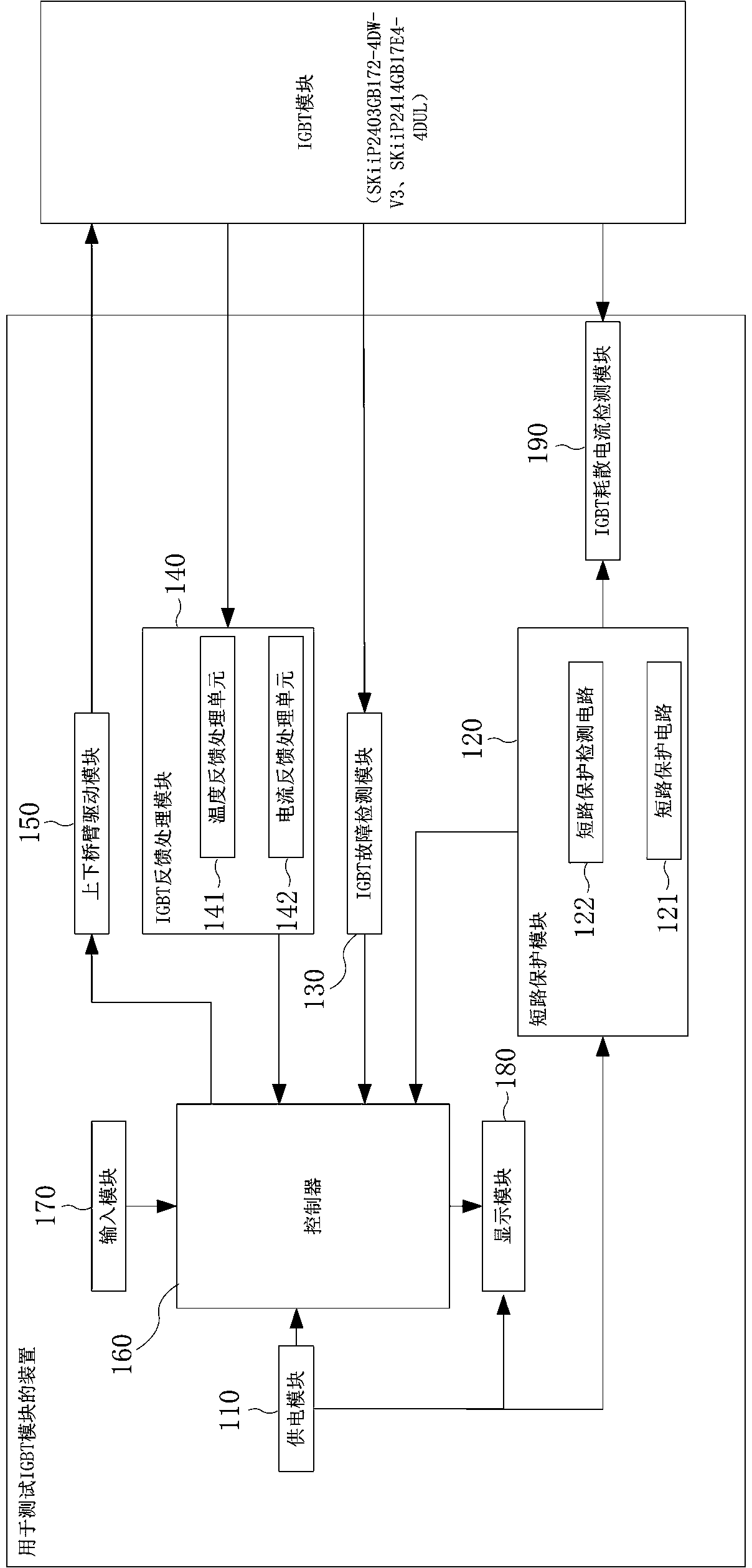
[0027] figure 1 is an apparatus for testing an IGBT module according to an exemplary embodiment of the present invention. Such as figure 1 As shown, the device for testing an IGBT module according to an exemplary embodiment of the present invention includes a power supply module 110, a short circuit protection module 120, an IGBT fault detection module 130, an IGBT feedback processing module 140, an upper and lower bridge arm drive module 150, and a controller 160 , an input module 170 , a display module 180 and an IGBT dissipation current detection module 190 .

[0028] At the same time, if figure 1 As shown, the short circuit protection module 120 includes a short cir...


PUM


Abstract

The invention provides a device for testing an insulated gate bipolar translator (IGBT) module. The device comprises a controller, an driving module of an upper bridge arm and a lower bridge arm, an IGBT dispersion current detecting module, and a short circuit protection module, wherein the controller is used for generating pulse width modulation (PWM) signals driving the IGBT module, the driving module of the upper bridge arm and the lower bridge arm transfers the PWM signals generated by the controller into the PWM signals suitable to drive the IGBT module, the IGBT dispersion current detecting module is used for detecting the dispersion current of the IGBT module, and the short circuit protection module prevents the short circuit of the power supply provided to the dispersion current detecting module and transmits signals that the power supply is in short circuit to the controller. According to the device for testing the IGBT module with the mentioned structure, system detecting cost can be reduced, safe, reliable, convenient and a suitable testing tool and a method are provided, and therefore the IGBT testing can be completed without expensive testing equipment, testers have no electric shocking hazard, and the device for testing the IGBT module is safe and reliable.

Description

technical field [0001] The invention relates to a device for testing an IGBT module, more specifically, to a safe and reliable device for testing an IGBT module without any risk of electric shock to testers. Background technique [0002] IGBT is an indispensable power device in the power electronics and electrical industry. It has been more and more widely used in modern power electronics technology, and it occupies a dominant position in high-frequency and medium-power applications. However, for this The test method of high-power IGBT devices is always based on the test conditions of high voltage and high current to complete the test. [0003] For example, the existing IGBT test method is based on the "H" bridge for testing, the topology of the hardware is as follows Figure 6 As shown, the three-phase AC is rectified into DC by diodes to provide energy for the busbar support capacitor. The busbar is connected with two IGBT units to form an "H" bridge. In order to minimize ...

Claims


Application Information

Patent Timeline
Patent Type & Authority Applications(China)
IPC IPC(8): G01R31/26
Inventor 岳健
Owner BEIJING GOLDWIND SCI & CREATION WINDPOWER EQUIP CO LTD
Why Eureka
Try Eureka