LED candle lamp dissipating heat by utilizing bottom-up free mobility of air

An LED candle light, bottom-up technology, applied in the direction of lampshade, lighting and heating equipment, components of lighting devices, etc., can solve the problem that the heat dissipation effect of the LED candle light cannot reach an ideal state, the working efficiency of the LED candle light is not high, Electromagnetic interference is difficult to deal with and other problems, to achieve the effect of scientific and reasonable heat dissipation design, rapid and effective heat dissipation, and good electromagnetic interference problems

Inactive Publication Date: 2014-01-15
李锡文 +1
View PDF7 Cites 6 Cited by
  • Summary
  • Abstract
  • Description
  • Claims
  • Application Information

AI Technical Summary

Problems solved by technology

The traditional heat dissipation method of LED candle lights is that the heat generated by the LED light source is transmitted downwards to the metal shell, and then the heat is released into the air through the metal shell to achieve the heat dissipation effect of the lamps. However, in daily life, LED candle lights are generally used as light sources. It is installed vertically upwards, and from the principle of thermodynamics, heat flows from bottom to top, so the heat dissipation effect of traditional LED candle lamps cannot reach the ideal state
At the same time, in order to avoid the risk of electric shock caused by the metal shell of the traditional LED candle lamp, this kind of LED candle lamp must use the drive power of the isolated circuit, and the isolated drive power will also generate a lot of heat when it is working, resulting in a higher temperature of the shell. At the same time, the work efficiency of LED candle lamps using isolated drive power is not high, and electromagnetic interference is also difficult to deal with

Method used


Image

  • LED candle lamp dissipating heat by utilizing bottom-up free mobility of air
  • LED candle lamp dissipating heat by utilizing bottom-up free mobility of air
  • LED candle lamp dissipating heat by utilizing bottom-up free mobility of air

Examples


Embodiment Construction

[0010] The present invention will be further described below in conjunction with specific embodiment:

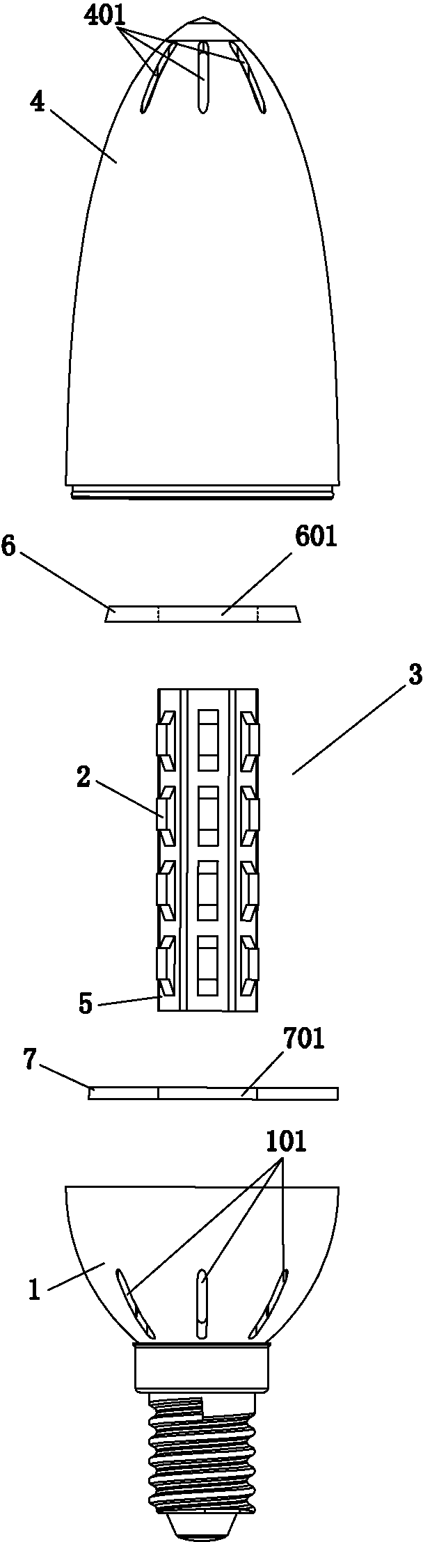
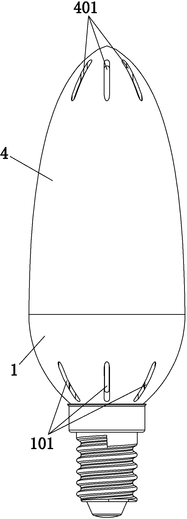
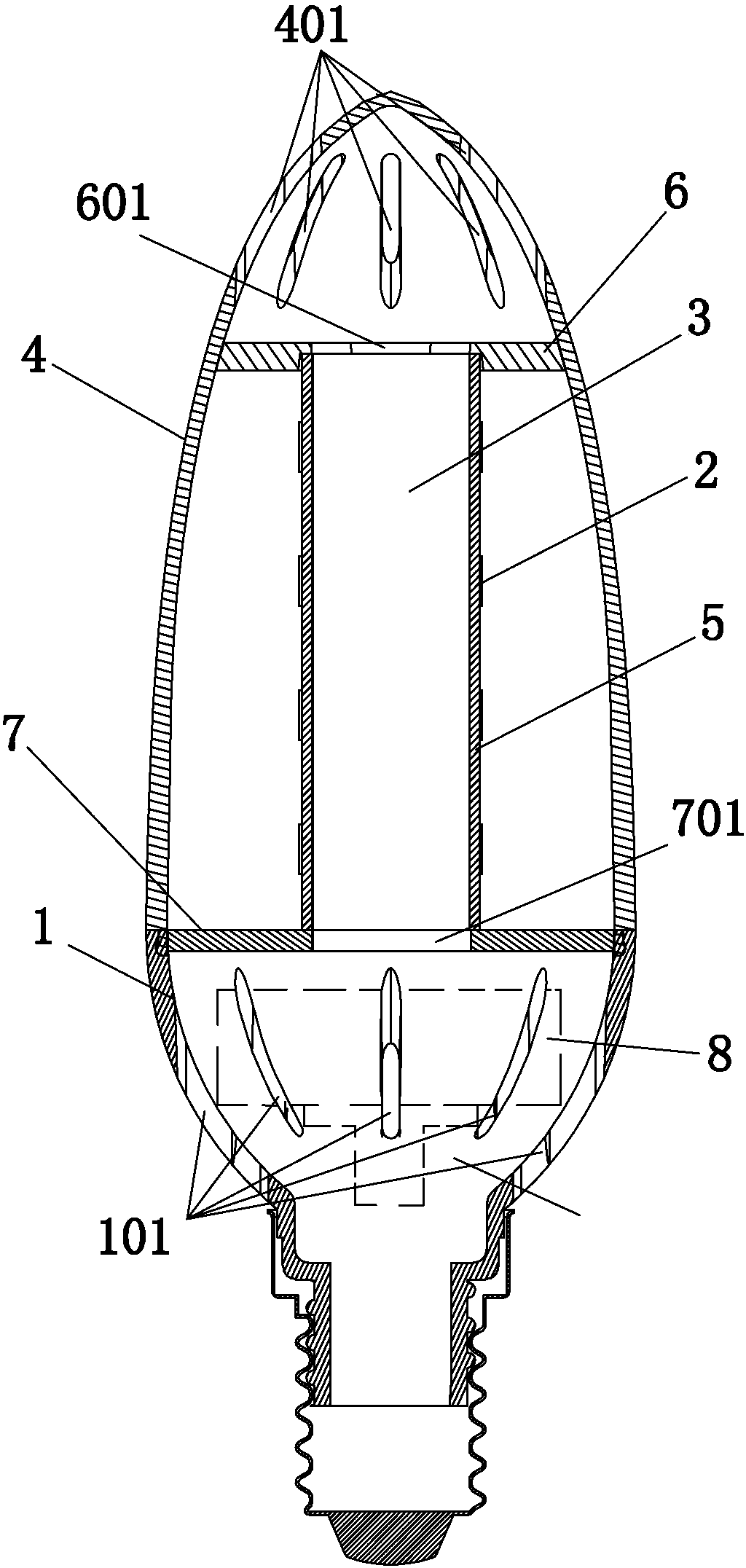
[0011] See attached figure 1 To attach image 3 As shown, the LED candle lamp described in this embodiment uses air to flow freely from bottom to top to dissipate heat, which includes a lamp cup 1, LED lamp beads 2, heat conducting columns 3, an upper partition 6, a metal lower partition 7, Candle-shaped lampshade 4 and flexible circuit board 5, LED lamp beads 2 are arranged on the flexible circuit board 5, and the flexible circuit board 5 is closely attached to the surface of the heat conduction column 3, and there is a slot inside the lamp cup 1, which is fixedly placed on the slot The LED power supply 8 corresponding to the slot, the heat conduction column 3 is a cylindrical structure that penetrates up and down, the upper partition 6 is provided with an upper ventilation hole 601, and the metal lower partition 7 is provided with a lower ventilation hole 701. The heat co...


PUM


Abstract

The invention provides an LED candle lamp dissipating heat by utilizing bottom-up free mobility of air. The LED candle lamp comprises a lamp cup, LED lamp beads, a heat conducting column, a candle-shaped lampshade and a flexible circuit board. The LED lamp beads are installed on the flexible circuit board. The flexible circuit board is tightly attached to the surface of the heat conducting column in a surrounding mode. The candle-shaped lampshade and the lamp cup are fixedly assembled. The LED candle lamp further comprises an upper partition plate and a lower metal partition plate. An upper vent hole is formed in the upper partition plate. A lower vent hole is formed in the lower metal partition plate. The heat conducting column is of a cylindrical structure which is vertically communicated. The upper vent hole in the upper partition plate and an upper port in the heat conducting column are assembled in a matched mode. The lower vent hole in the lower metal partition plate and a lower port in the heat conducting column are assembled in a matched mode. A plurality of air inlet holes are formed in the lamp cup. A plurality of air outlet holes are formed in the candle-shaped lampshade. A ventilation and heat dissipation system with air flowing from bottom to top is composed of the air inlet holes, the lower vent hole, the heat conducting column, the upper vent hole and the air outlet holes. The LED candle lamp has the advantages that the heat is dissipated during free convection of the air to the exterior of a lamp body, the heat is rapidly dissipated, and the effect is good.

Description

technical field [0001] The invention relates to the technical field of lighting fixtures, in particular to an LED candle lamp which uses air to freely flow from bottom to top to dissipate heat. Background technique [0002] Currently available LED candle lamps on the market, the structure of the candle lamp is that the upper part is an LED light source and a candle-like lampshade, and the lower part is a metal shell with thermal conductivity and a built-in power supply for heat dissipation. The traditional heat dissipation method of LED candle lights is that the heat generated by the LED light source is transmitted downwards to the metal shell, and then the heat is released into the air through the metal shell to achieve the heat dissipation effect of the lamps. However, in daily life, LED candle lights are generally used as light sources. It is installed and used vertically upwards, and from the principle of thermodynamics, heat flows from bottom to top, so the heat dissipa...

Claims


Application Information

Patent Timeline
Patent Type & Authority Applications(China)
IPC IPC(8): F21S2/00F21V29/00F21V3/04F21Y101/02F21K9/235F21V29/71F21V29/83F21Y115/10
Inventor 李锡文武建忠
Owner 李锡文
Why Eureka
Try Eureka